Electric power system fault diagnosis method based on topology analysis
A power system and fault diagnosis technology, which is applied in the power network operating system integration, transmission system, fault location and other directions, can solve problems such as abnormal operation status and fault, and achieve the effect of efficient fault handling
- Summary
- Abstract
- Description
- Claims
- Application Information
AI Technical Summary
Problems solved by technology
Method used
Image
Examples
Embodiment 1
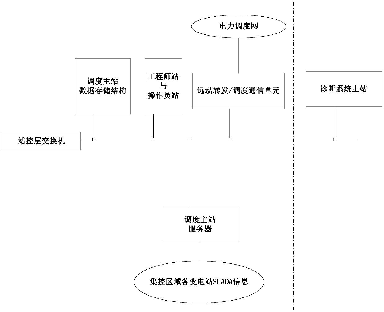
[0028] Please refer to figure 1 and figure 2 , showing a power system fault diagnosis expert system provided by the present invention.
[0029] The power system fault diagnosis expert system includes a master station of the diagnosis system, and the master station of the diagnosis system in this embodiment is directly set up by using the network of the dispatcher master station (or called centralized control master station) (hereinafter collectively referred to as the dispatcher master station).
[0030] figure 1 In the figure, the left side of the dotted line is the structure of the dispatching master station, and the right side of the dotted line is the master station of the diagnosis system of the fault diagnosis expert system.
[0031] Depend on figure 1 It can be seen that the main station of the diagnosis system in this embodiment is installed in the network structure of the dispatching main station.
[0032] Such as figure 1 As shown, the corresponding dispatching...
Embodiment 2
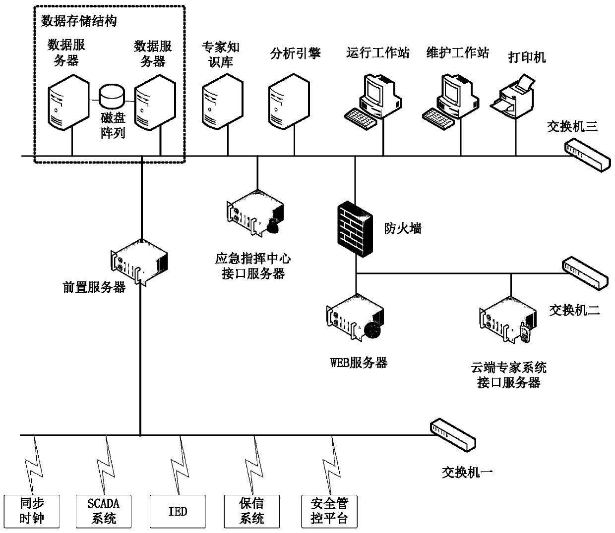
[0056] Please refer to image 3 , shows another power system fault diagnosis expert system provided by the present invention.
[0057] Most of the structures of the fault diagnosis expert system provided by this embodiment are the same as those of the foregoing embodiments, therefore, corresponding contents of the foregoing embodiments can be referred to in conjunction.
[0058] These include the same parts of the main station of the diagnostic system, specifically the main station of the diagnostic system includes: data storage structure, expert knowledge base, front server, analysis engine and operating workstation; among them, the data storage structure can include data servers and disk arrays ; In addition, it also includes maintenance workstation, emergency command center interface server, WEB server, cloud expert system interface server, firewall, network equipment and output device (the output device can be specifically a printer), etc.; through the front server, the ma...
Embodiment 3
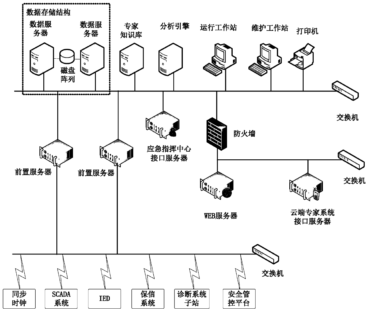
[0066] Please refer to Figure 4 , shows another power system fault diagnosis expert system provided by the present invention.
[0067] Most of the structures of the fault diagnosis expert system provided by this embodiment are the same as those of the foregoing embodiments, therefore, corresponding contents of the foregoing embodiments can be referred to in conjunction.
[0068] These same structures include the corresponding structure of the master station of the diagnosis system, specifically the master station of the diagnosis system includes: data storage structure, expert knowledge base, front server, analysis engine and operating workstation; wherein, the data storage structure may include a data server and disk arrays; in addition, it also includes maintenance workstations, emergency command center interface servers, WEB servers, cloud expert system interface servers, firewalls, network equipment, and output devices (specifically, output devices can be printers), etc.;...
PUM
 Abstract
Description
Claims
Application Information
 - R&D
- Intellectual Property
- Life Sciences
- Materials
- Tech Scout
- Unparalleled Data Quality
- Higher Quality Content
- 60% Fewer Hallucinations
Browse by: Latest US Patents, China's latest patents, Technical Efficacy Thesaurus, Application Domain, Technology Topic, Popular Technical Reports.
© 2025 PatSnap. All rights reserved.Legal|Privacy policy|Modern Slavery Act Transparency Statement|Sitemap|About US| Contact US: help@patsnap.com


