
Numerical control lathe with automatic feeding and discharging structure
A technology of automatic loading and unloading and CNC lathes, applied in the field of CNC lathes, can solve the problems of being unsuitable for popularization and use, unsuitable for shaft parts, unable to meet the production of small and medium-sized batches of multi-specification shaft parts, etc., to avoid failures that cannot be handled in time Effect
Patent Information
- Authority / Receiving Office
- CN · China
- Current Assignee / Owner
- Publication Date
- 2020-06-26
Smart Images
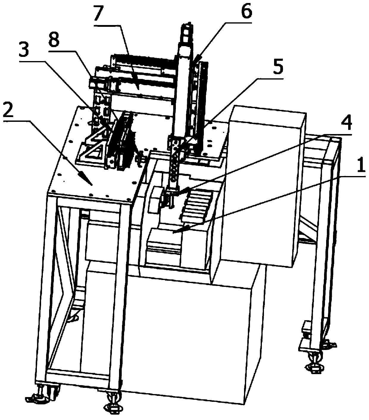
Figure 1 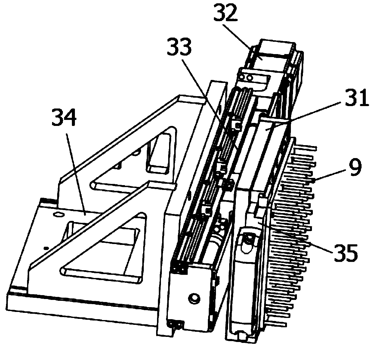
Figure 2 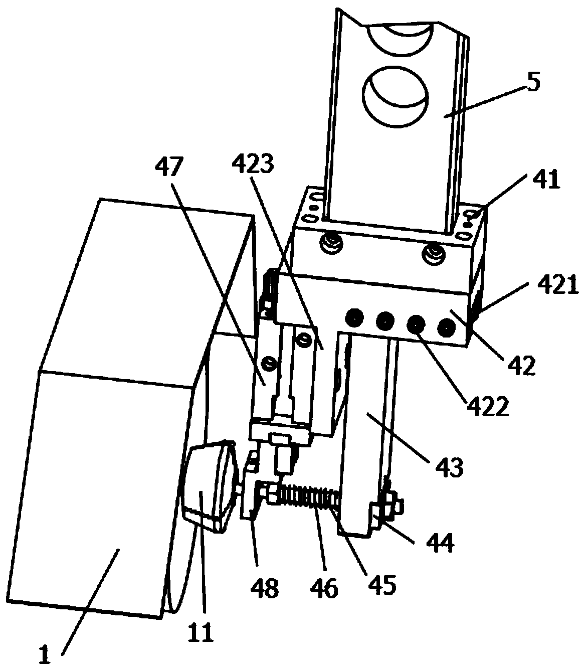
Figure 3
Abstract
Description
technical field
[0001] The invention belongs to the technical field of lathe numerical control processing, in particular to a numerical control lathe with an automatic loading and unloading structure. Background technique
[0002] In lathe CNC machining, in order to save human resources and reduce labor intensity, people have designed a variety of automatic loading and unloading devices for lathes. At present, most of them are used for automatic loading and unloading of round lathe bars. Most of these parts are formed at one time. However, it is not applicable to shaft parts for secondary processing. There are also some application cases for the automatic loading and unloading device of the lathe for secondary processing, such as patent No. CN201510132876.6 and CN201821087191. Both adopt the direct push type of vibrating plate feeding to feed the jaws of the lathe. The direct pushing methods of the two devices are different. The vibrating plate is effective for a single pro...
Examples
Embodiment Construction
[0027] In order to make the object, technical solution and advantages of the present invention more clear, the present invention will be further described in detail below in conjunction with the examples. It should be understood that the specific embodiments described here are only used to explain the present invention, not to limit the present invention.
[0028] A numerical control lathe with an automatic loading and unloading structure, comprising a lathe 1; lathe jaws 11 are installed inside the lathe 1; a support platform 2 is installed on the top of the lathe 1, and a rod is installed on the surface of the support platform 2 Material storage mechanism 3, Y-axis motion assembly 7 and material receiving mechanism 8; The X-axis direction of the bar stock storage mechanism 3 is provided with the Y-axis motion assembly 7, and the Y-axis direction of the bar stock storage mechanism 3 is provided with The receiving mechanism 8; the receiving mechanism 8 is located on the side o...