
Sectional insulator and contact rail system

A segmented insulator and segmented insulation technology, which is applied in the direction of power rails, overhead lines, etc., can solve the problems of segmental insulators, such as channeling, and achieve the effects of avoiding channeling, improving work safety, and ensuring safety

Active Publication Date: 2020-06-26
HUNAN HUAPIN RAIL TRANSIT CO LTD
View PDF7 Cites 0 Cited by
  • Summary
  • Abstract
  • Description
  • Claims
  • Application Information

AI Technical Summary

Problems solved by technology

[0004] The purpose of the embodiments of the present application is to provide a segmented insulator to solve the technical problem that the segmented insulator is prone to channeling in the prior art

Method used


Image

  • Sectional insulator and contact rail system
  • Sectional insulator and contact rail system
  • Sectional insulator and contact rail system

Examples


Embodiment 1

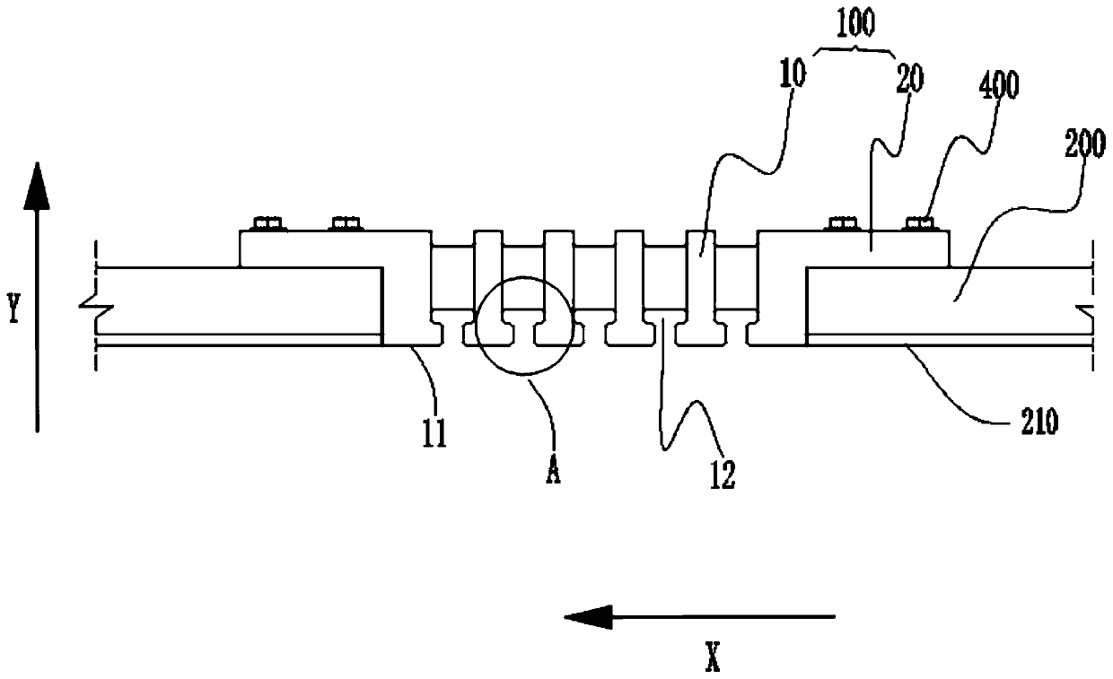
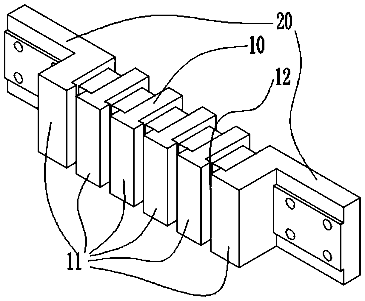
[0038] Please also refer to figure 1 and figure 2 , the segmented insulator 100 provided by the embodiment of the present application will now be described. The segment insulator 100 is used in a busbar system to realize an insulated connection between busbar segments 200 .

[0039] see figure 1 , the segmented insulator 100 has a first working surface 11, correspondingly, the contact rail segment 200 at both ends has a second working surface 210, the first working surface 11 and the second working surface 210 are flush with each other, the first working surface Both the surface 11 and the second working surface 210 are used for sliding the power receiving shoe 300 . Specifically, the first working surface 11 and the second working surface 210 are both figure 1 When working, the power receiving shoe 300 alternately slides on the first working surface 11 and the second working surface 210 to realize power supply to each contact rail segment 200 .

[0040] A plurality of f...

Embodiment 2

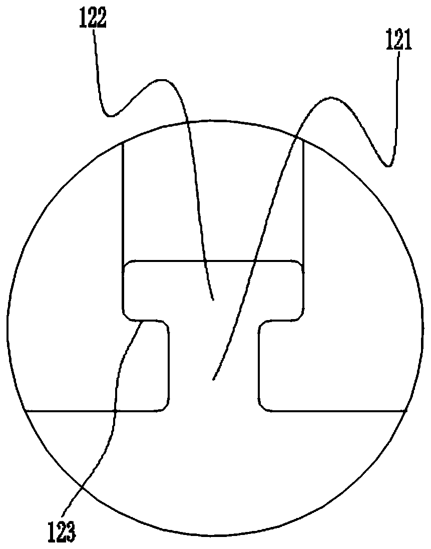
[0055] The technical features of the segmented insulator 100 in this embodiment are basically the same as those of a segmented insulator 100 in the embodiment, the difference is that in this embodiment, please refer to Figure 7 , along the depth direction of the first groove 12, the width of the second groove segment 122 along the sliding direction of the power receiving shoe 300 first gradually increases, and then gradually decreases. Moreover, the first cross section of the second groove segment 122 is connected by an arc segment, specifically an ellipse.

Embodiment 3

[0057] The technical features of the segmented insulator 100 in this embodiment are basically the same as those of a segmented insulator 100 in the embodiment, the difference is that in this embodiment, please refer to Figure 8 , along the depth direction of the first groove 12 , the width of the second groove segment 122 gradually increases along the sliding direction of the power receiving shoe 300 . In addition, the first section of the second slot section 122 is connected by an arc section and a straight section, which is T-shaped specifically, and the top end is provided with rounded corners of the arc section.


PUM


Abstract

The invention relates to the technical field of rail transit contact rail systems, and provides a sectional insulator which is provided with a first working surface for a power receiving shoe to slide, a plurality of first grooves are formed in the first working surface, and the first grooves are distributed at intervals in the sliding direction of the power receiving shoe; the first groove comprises a first groove section and a second groove section which are sequentially distributed in the depth direction of the first groove, and a step used for preventing conductive dust from escaping fromthe second groove section to the first groove section is formed between the second groove section and the first groove section. The invention further provides a contact rail system. The contact rail system comprises the section insulator and a contact rail section. According to the section insulator provided by the invention, the phenomenon of power channeling between adjacent power supply sections can be avoided, and thus the safety of personnel in the operation and maintenance process is ensured.

Description

technical field [0001] The application belongs to the technical field of rail transit contact rail systems, and more specifically relates to a segmented insulator and contact rail system. Background technique [0002] In the field of rail transit, some standard lines use the contact rail segment to supply power to the vehicle, and the segment insulator is an insulation device used when the contact rail is segmented for electrical segmentation. Under normal circumstances, the electrified shoe slides through. When a fault occurs in a certain contact rail section or the power is cut off due to construction, the isolation switch at the section insulator is turned on to cut off the power supply of the part of the catenary, while other parts can work normally and supply power. [0003] However, during long-term use, the conductive particles generated by the friction of the electric shoes will adhere to the inner wall of the channel, affecting the electrical insulation performance ...

Claims


Application Information

Patent Timeline
Patent Type & Authority Applications(China)
IPC IPC(8): B60M1/18B60M1/30
CPCB60M1/18B60M1/30
Inventor 占立泽
Owner HUNAN HUAPIN RAIL TRANSIT CO LTD
Learn More