Tray and material utensil storing method and equipment of continuous thermal treatment production line

A production line and continuous technology, applied in the direction of conveyors, mechanical conveyors, transportation and packaging, etc., can solve problems such as low production efficiency, confusion in the storage area of ​​trays and tools, and delays in production

Pending Publication Date: 2020-06-26
爱协林热处理系统(北京)有限公司
View PDF0 Cites 0 Cited by
  • Summary
  • Abstract
  • Description
  • Claims
  • Application Information

AI Technical Summary

Problems solved by technology

[0003] To deal with different heat treatment workpieces, various trays and tools are required. For the trays and tools, a fixed tray and tools storage area 5 is set separately. Generally, the trays and tools storage area 5 is set next to the heat treatment workpiece storage area. , when necessary, transfer the trays and tools to the loading table 2 of the continuous heat treatment production line 1 by hand or by trolley. Since there are various types of trays and tools, and the old and new are stacked together, once the management is neglected, the trays will be damaged. The tool storage area 5 is very chaotic and delays production
[0004] In addition, the tray and material storage area 5 is relatively far away from the continuous heat ...

Method used


Image

  • Tray and material utensil storing method and equipment of continuous thermal treatment production line
  • Tray and material utensil storing method and equipment of continuous thermal treatment production line
  • Tray and material utensil storing method and equipment of continuous thermal treatment production line

Examples


Embodiment Construction

[0020] The specific embodiments of the present invention will be further described in detail below in conjunction with the accompanying drawings.

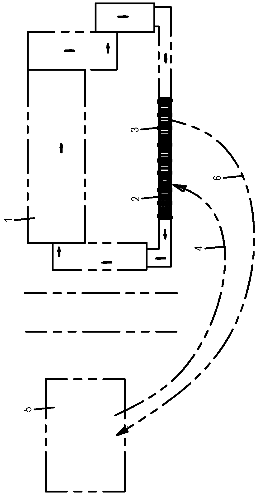
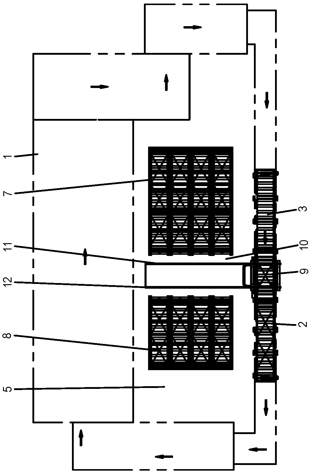
[0021] Such as Figure 2-Figure 3 shown.

[0022] The method for storing trays and tools in a continuous heat treatment production line according to the present invention includes placing the trays and tools on the stocking table group 7, placing the heat-treated workpieces on the corresponding trays, and placing the stocking table group 7 on the platform. On the rack 8, the rack 8 is neatly placed in the tray and material storage area 5 in the middle of the ring circle of the continuous heat treatment production line 1, and the storage tray group 7 loaded with the tray and tools is transferred to the feeding platform by the turnover trolley 9. Between 2 and the unloading table 3, push the tray material to the loading table 2, place the heat-treated workpiece on the corresponding tray material, and push the tray material to comple...


PUM


Abstract

The invention relates to a tray and material utensil storing method and equipment of a continuous thermal treatment production line. A tray and a material utensil are placed on a tray storing materialplatform group; thermal treatment workpieces are placed on a corresponding tray and a corresponding material utensil; the tray storing material platform group is placed on a bench; the bench is placed in a tray and material utensil storing area in order in the middle of the annular ring of the continuous thermal treatment production line; a turnover trolley is adopted to transfer the tray storingmaterial platform group loaded with the tray and the material utensil between a feeding platform and a discharging platform and push the tray and the material utensil on the feeding platform. Throughthe technical scheme, the situation that the tray and the material utensil are carried up and down is effectively eliminated, the tray and the material utensil can be stacked in the annular ring of the continuous thermal treatment production line in order through the tray storing material platform group, so that management and application of the tray and the material utensil are facilitated, thetransferring distance is greatly shortened, realization of automation is facilitated, the situation that the tray and material utensil storing area is additionally arranged outside the annular ring isavoided, and the land utilization ratio is effectively increased.

Description

technical field [0001] The invention relates to a continuous heat treatment production line, in particular to a method and equipment for storing material trays and tools in the continuous heat treatment production line. Background technique [0002] In the existing technology, such as figure 1 As shown, the continuous heat treatment production line 1 is arranged in a ring, and the continuous heat treatment production line 1 is provided with a loading platform 2 and a discharge platform 3. When working, it is necessary to place unnecessary trays and tools on the discharge platform 3 From the unloading platform 3 to the tray material storage area 5 through the return route 4, and at the same time, the required tray material storage area 5 is sent to the loading platform 2 through the feeding route 6 Then place each heat-treated workpiece on the tray material, and push the tray material with the heat-treated workpiece into it for heat treatment. [0003] To deal with differen...

Claims


Application Information

Patent Timeline
IPC IPC(8): B65G35/00B65G37/00
CPCB65G35/00B65G37/00
Inventor 王召金
Owner 爱协林热处理系统(北京)有限公司
Why Eureka
Try Eureka