Forklift with locking mechanism
A locking mechanism, forklift technology, applied in the direction of the lifting device, etc., to achieve the effect of easy use, convenient length, convenient adjustment
- Summary
- Abstract
- Description
- Claims
- Application Information
AI Technical Summary
Problems solved by technology
Method used
Image
Examples
Embodiment 1
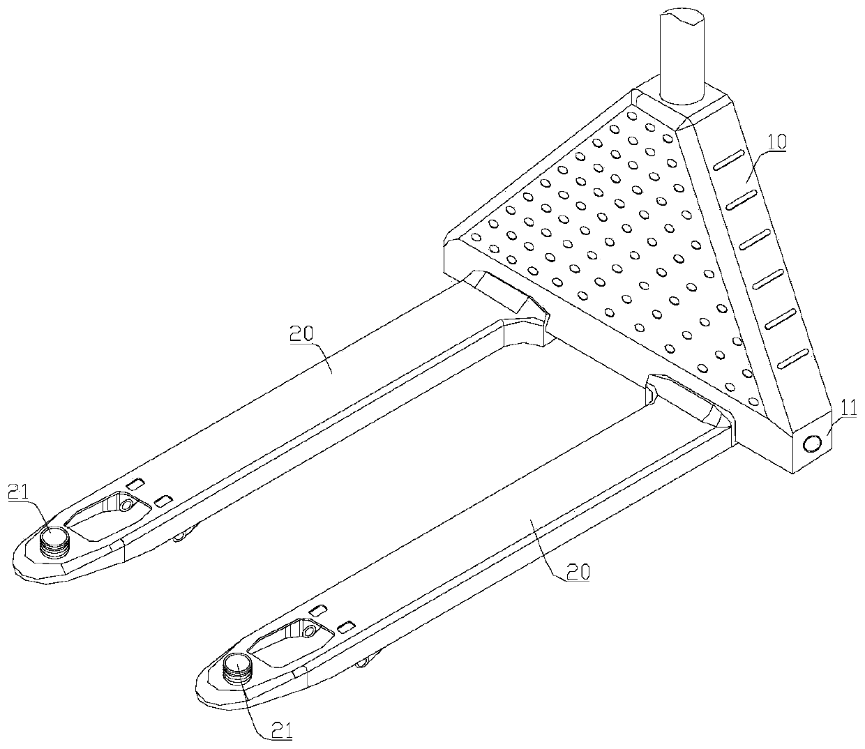
[0043] Such as figure 1 As shown, it is a structural schematic diagram of a forklift with a locking mechanism according to a preferred embodiment of the present invention. The above-mentioned forklift includes a forklift assembly 10 and a forklift frame 20 installed at the bottom thereof, and the forklift frame 20 is installed There is a connecting column 21, and external threads are distributed on the outer wall of the connecting column 21;
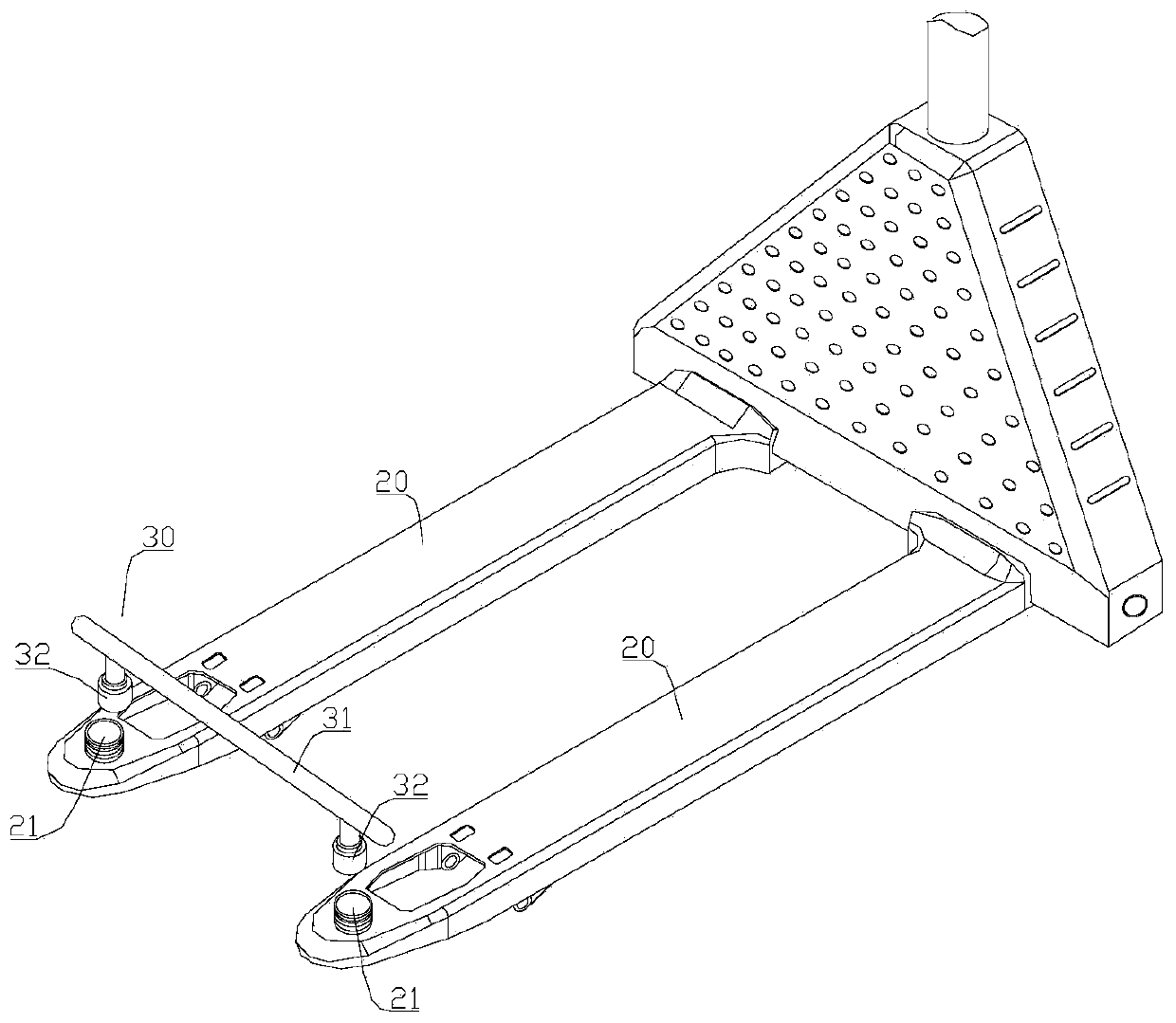
[0044] Such as figure 2 As shown, the above-mentioned forklift also includes a locking mechanism 30 for locking goods. The locking mechanism 30 includes a crossbeam 31 and a connecting sleeve 32 symmetrically installed at the bottom of the crossbeam 31. The connecting sleeve 32 and the crossbeam 31 Rotate connection, and the connecting sleeve 32 is open at the bottom and the inner wall is distributed with internal threads that match the external threads on the connecting column 21, and the connecting sleeve 32 is located directly above...
Embodiment 2
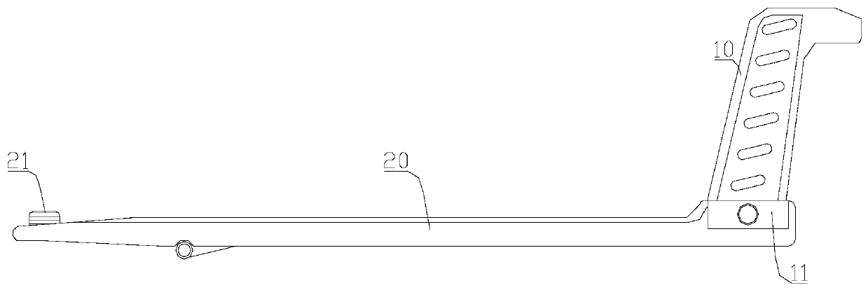
[0047] Such as image 3 as well as Figure 5 As shown, it is a structural schematic diagram of a forklift with a locking mechanism in another preferred embodiment of the present invention; on the basis of Example 1, the bottom of the forklift assembly 10 is provided with a mounting part 11, and the mounting part 11 is a hollow structure with an opening at the bottom. An adjusting screw 12 is rotatably installed in the mounting portion 11. One end of the adjusting screw 12 is rotatably mounted on the side wall of the mounting portion 11. The other end of the adjusting screw 12 extends out of the The mounting part 11 is connected with a rotating handle, and the adjusting screw 12 is rotatably connected with the mounting part 11, and the directions of threads distributed on the adjusting screw 12 are opposite;
[0048] Such as Figure 6As shown, the end of the forklift frame 20 close to the forklift assembly 10 is integrally formed with a mounting groove 22, the mounting groove...
Embodiment 3
[0054] Such as Figure 8 as well as Figure 9 As shown, it is a schematic structural diagram of a forklift with a locking mechanism in another preferred embodiment of the present invention. On the basis of Example 1 or Example 2, the forklift frame 20 includes a fixed forklift frame 23 and The movable forklift frame 24, the fixed forklift frame 23 is an internal hollow structure, and a driving cylinder 25 is installed on the inner wall of the fixed forklift frame 23, and the driving cylinder 25 is electrically connected with the control system on the outside of the forklift. The system controls the drive cylinder 25 to work. A movable forklift frame 24 is slidably installed on the fixed forklift frame 23. The movable forklift frame 24 is sleeved on the fixed forklift frame 23, and the fixed forklift frame 23 is far away from the forklift assembly 10 A stopper is installed at one end of the stopper, and the stopper prevents the sliding of the movable forklift frame 24 from the...
PUM
 Abstract
Description
Claims
Application Information
 - R&D
- Intellectual Property
- Life Sciences
- Materials
- Tech Scout
- Unparalleled Data Quality
- Higher Quality Content
- 60% Fewer Hallucinations
Browse by: Latest US Patents, China's latest patents, Technical Efficacy Thesaurus, Application Domain, Technology Topic, Popular Technical Reports.
© 2025 PatSnap. All rights reserved.Legal|Privacy policy|Modern Slavery Act Transparency Statement|Sitemap|About US| Contact US: help@patsnap.com


