
Lining trolley and tunnel secondary lining construction method using lining trolley

A technology for lining trolleys and trolleys, which is applied in tunnels, shaft linings, tunnel linings, etc., can solve the problems of heavy labor burden on construction personnel, affecting the efficiency of secondary lining construction, and slow adjustment speed.

Active Publication Date: 2020-06-26
陕西交通科技有限公司
View PDF6 Cites 4 Cited by
  • Summary
  • Abstract
  • Description
  • Claims
  • Application Information

AI Technical Summary

Problems solved by technology

[0004] The above-mentioned existing technical solutions have the following defects: when the trolley side formwork, top formwork pouring and vault belt formwork grouting are carried out in sequence, the position of the grout delivery pipe needs to be manually adjusted, which imposes a heavy labor burden on the construction personnel, and The adjustment speed is slow, which affects the efficiency of secondary lining construction

Method used


Image

  • Lining trolley and tunnel secondary lining construction method using lining trolley
  • Lining trolley and tunnel secondary lining construction method using lining trolley
  • Lining trolley and tunnel secondary lining construction method using lining trolley

Examples


Embodiment 1

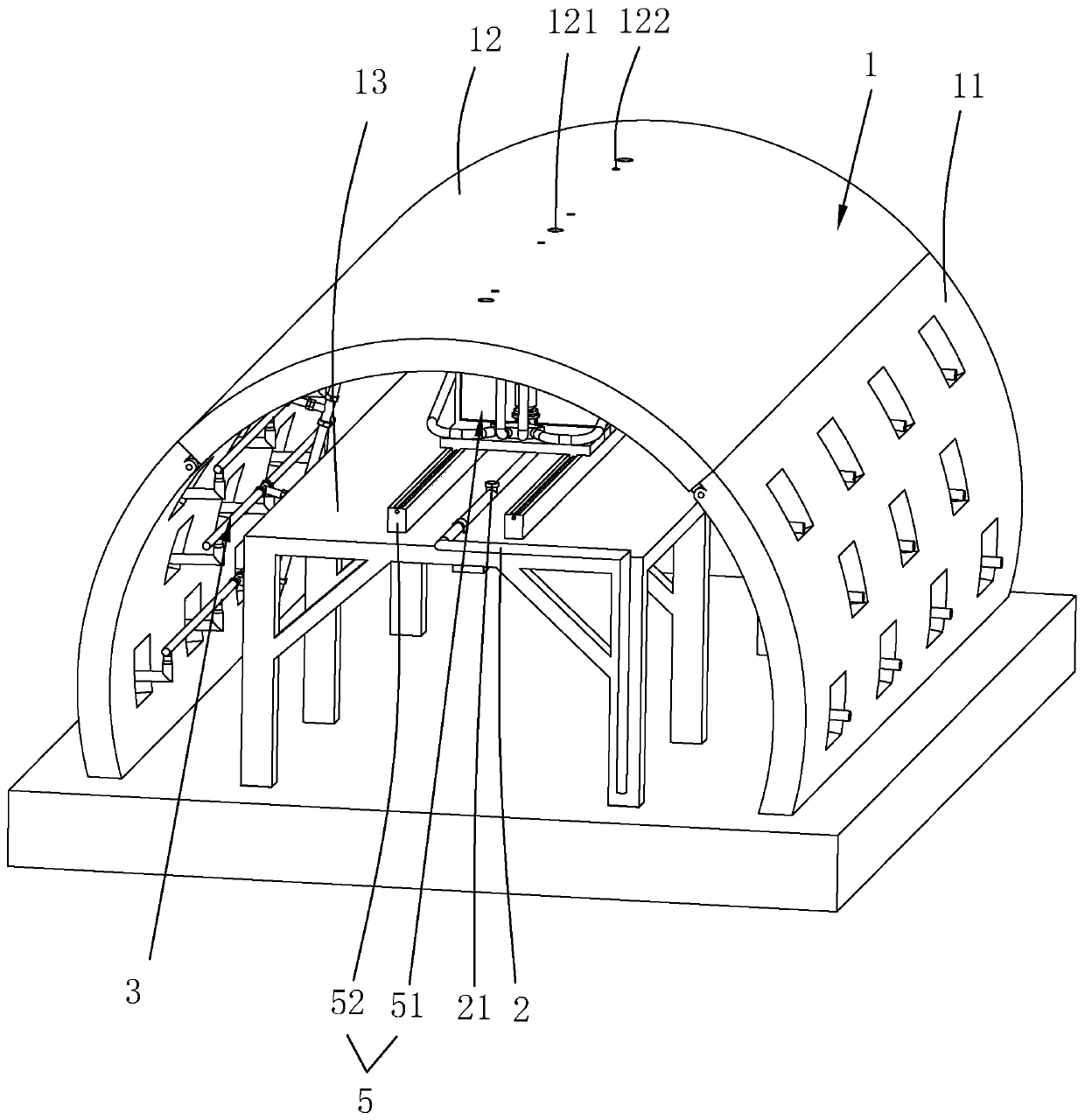
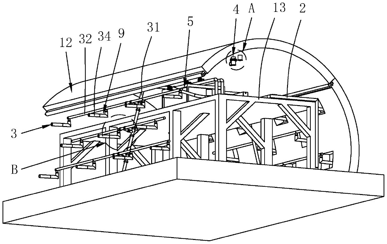
[0051] refer to figure 1 , is a lining trolley disclosed by the present invention, comprising a trolley body 1, a hinged side form 11 and a top form 12 are installed on the outside of the trolley body 1, and top form pouring pipes are arranged at intervals along the centerline direction on the top form 12 121 and belt mold grouting port 122, the trolley body 1 is also equipped with a slurry delivery pipe 2 and a side mold pouring pipeline 3, and a number of slurry outlets 21 are installed on the slurry delivery tube 2, and the slurry outlets 21 correspond to the side molds respectively. The pouring pipeline 3 feed inlet, the top mold pouring pipe 121 and the molded grouting port 122 are arranged. The trolley body 1 is also welded with a bearing platform 13 below the top form 12, and the integrated casting module 5 is arranged on the bearing platform 13.

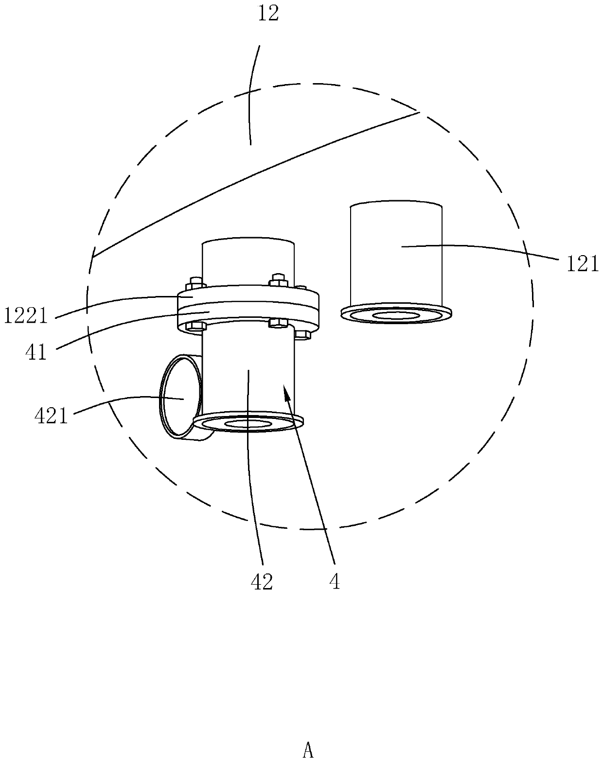
[0052] refer to figure 2 and image 3 , a fixed flange 1221 is arranged on the inner side of the belt mold grouting por...

Embodiment 2

[0064] A method for constructing the second lining of a tunnel, using the lining trolley in Embodiment 1, comprising the following steps:

[0065] S1. Install the second-lined steel bars, chisel and rinse the concrete on the surface of the joint between the inverted arch and the second-lined, bind the main reinforcement and stirrups of the second-lined, and when binding the toe of the wall and the steel bars of the inverted arch, encrypt the main reinforcement and place them on the near side Encrypt the protective layer pad on one side of the mold 11, and adjust the steel bar to a circular arc that can match the connection position of the bottom of the lining trolley and the inverted arch steel bar through the entire row of guy wires;

[0066] S2. The lining trolley is in place, the lining trolley walks to the position of the vertical mold, and is positioned by the total station to make the lining trolley accurately in place, the hydraulic jacking cylinder lifts the side formwo...


PUM


Abstract

The invention relates to a lining trolley which comprises a trolley body. Side molds and a top mold are arranged on the trolley body. A grout conveying pipe and side mold pouring pipelines are furtherarranged on the trolley body. The top mold is provided with a top mold pouring pipe and mold grouting openings, and the grout conveying pipe is provided with a grout outlet. An integrated pouring module is arranged on the trolley body. The integrated pouring module comprises an integrated pouring vehicle and a guide rail. The integrated pouring vehicle comprises a frame body and a temporary storage tank. A first telescopic conveying pipe is arranged on the temporary storage tank. Four second telescopic conveying pipes are arranged on the frame body. A tunnel secondary lining construction method includes the steps of secondary lining steel bar positioning, placement of the lining trolley, manufacturing and mounting of a mold grouting pipe, and pouring of concrete. According to the lining trolley and the tunnel secondary lining construction method using the lining trolley, the integrated pouring module is designed, so that the automation degree in the construction process is improved, the labor burden of constructors is reduced, time for secondary lining is shortened, and the construction efficiency is improved.

Description

technical field [0001] The invention relates to the technical field of tunnel construction, in particular to a lining trolley and a tunnel secondary lining construction method using the lining trolley. Background technique [0002] After the excavation of the tunnel, the original balance of the strata around the tunnel is destroyed, and the tunnel must be permanently supported with sufficient strength, that is, the tunnel lining. Composite lining is used in most tunnel lining constructions, and composite lining is divided into primary lining and secondary lining. After the excavation of the surrounding rock, first install the supporting steel frame on the interface of the surrounding rock of the section, and then spray concrete to form the primary lining. When the primary lining reaches the standard strength, the waterproof board will be constructed. The lining trolley is driven into place for secondary lining construction. At present, during the construction of the second...

Claims


Application Information

Patent Timeline
IPC IPC(8): E21D11/10
CPCE21D11/102E21D11/105E21D11/107
Inventor 王彦峰屈立勇韩晓洲李少康
Owner 陕西交通科技有限公司
Learn More