A kind of sealing equipment of grate cooler transmission mechanism for cement production

A transmission mechanism and sealing equipment technology, applied in lighting and heating equipment, processing discharged materials, furnaces, etc., can solve the problems of powder and other impurities that cannot be cleaned, and achieve the effect of improving adsorption, sealing effect and cleaning effect

Active Publication Date: 2022-07-15
SINOMA TECH (XUZHOU) HEAVY MASCH CO LTD
View PDF9 Cites 0 Cited by
  • Summary
  • Abstract
  • Description
  • Claims
  • Application Information

AI Technical Summary

Problems solved by technology

The sealing box in the above-mentioned patent has the following disadvantages: Impurities such as powder adhering to the drive shaft and the sealing box cannot be effectively cleaned

Method used


Image

  • A kind of sealing equipment of grate cooler transmission mechanism for cement production
  • A kind of sealing equipment of grate cooler transmission mechanism for cement production
  • A kind of sealing equipment of grate cooler transmission mechanism for cement production

Examples


Embodiment 1

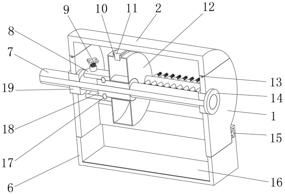
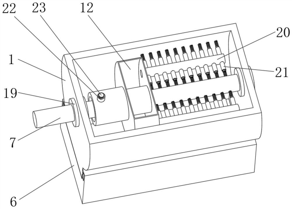
[0033] A sealing device for the transmission mechanism of a grate cooler for cement production, such as Figure 1-4 As shown, it includes a sealing chamber 1 fixed to the outer wall of one side of the equipment casing 3 by bolts and a fixing seat 18 fixed to the outer wall of the transmission shaft 7 by a jack screw; the inner wall of one side of the sealing chamber 1 is fixed with a first bearing seat A waterproof bearing 14, and a second waterproof bearing 19 is fixed on the inner wall of the other side of the sealing chamber 1 through a second bearing seat. The first waterproof bearing 14 and the second waterproof bearing 19 are both installed on the outer wall of the transmission shaft 7; the The outer wall of the fixing seat 18 is slidably connected with the water storage chamber 12 , two guide pipes 20 are welded on the outer wall of one side of the water storage chamber 12 , and several evenly distributed outer walls of the two guide pipes 20 are welded on both sides. T...

Embodiment 2

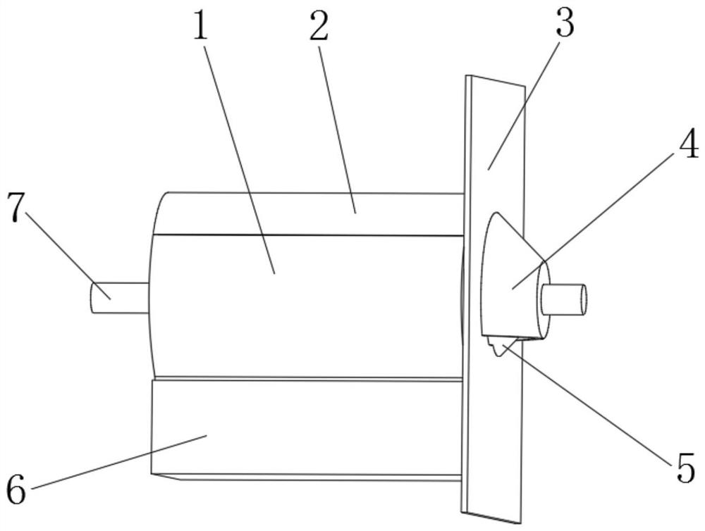
[0042] A sealing device for the transmission mechanism of a grate cooler for cement production, such as figure 1 , Image 6 As shown, in order to further dustproof; this embodiment makes the following improvements on the basis of Embodiment 1: an outer blocking cover 4 is welded on one side outer wall of the equipment casing 3, and an inner blocking cover 4 is welded on the same side outer wall of the equipment casing 3 Cover 5, the outer blocking cover 4 is arranged on the outside of the inner blocking cover 5, and the inner wall of one side of the outer blocking cover 4 and the inner wall of one side of the inner blocking cover 5 are all slidably connected to the outer wall of the transmission shaft 7; The blocking cover 5 can effectively block the internal dust from diffusing to the outside.

[0043] To reduce internal dust accumulation; such as Image 6 As shown, the bottom outer wall of the inner blocking cover 5 is provided with an ash discharge port 28 . By setting th...


PUM


Abstract

The invention discloses a sealing device for a transmission mechanism of a grate cooler for cement production, and relates to the technical field of cement production. In order to effectively clean impurities such as powder attached to a transmission shaft, it specifically includes fixing on one side of an equipment shell by bolts. The sealing chamber of the outer wall and the fixing seat fixed to the outer wall of the transmission shaft by the top wire, the inner wall of one side of the sealing chamber is fixed with the first waterproof bearing through the first bearing seat, and the inner wall of the other side of the sealing chamber is fixed through the second bearing seat A second waterproof bearing is fixed, and both the first waterproof bearing and the second waterproof bearing are installed on the outer wall of the transmission shaft; the outer wall of the fixed seat is slidably connected with a water storage chamber. The invention can clean the surface of the transmission shaft while sealing by arranging structures such as a brush, a brush head seat and a guide tube; The driveability of the drive shaft increases the controllability of the cleaning work.

Description

technical field [0001] The invention relates to the technical field of cement production, in particular to a sealing device of a grate cooler transmission mechanism for cement production. Background technique [0002] At present, cement production is a well-known industry. In the cement production process, the grate cooler is an important host equipment in the cement clinker firing system. Its main function is to cool and transport the cement clinker; The furnace, etc. provides hot air, which is the main equipment for heat recovery of the firing system; however, during the use of the grate cooler, a series of harmful phenomena such as dust leakage are likely to occur at the transmission mechanism of the grate cooler, so the tightness of the transmission mechanism is also very important. A point of concern. [0003] After searching, the Chinese patent application number CN201120374163.8 discloses a sealing device for the transmission mechanism of the grate cooler. The sealin...

Claims


Application Information

Patent Timeline
Patent Type & Authority Patents(China)
IPC IPC(8): F27D15/02F27D25/00C04B7/47
CPCF27D15/02F27D25/008C04B7/47
Inventor 马孝直何伟周建王玉红朱耿武许艳玲卢新丽
Owner SINOMA TECH (XUZHOU) HEAVY MASCH CO LTD
Why Eureka
Try Eureka