Check patentability & draft patents in minutes with Patsnap Eureka AI!

Explosion-proof joint surface gap online detection method and device based on machine vision

A machine vision and joint surface technology, applied in measuring devices, optical devices, instruments, etc., can solve problems such as high cost, applicable conditions, harsh working environment requirements, and unsuitable for daily inspection of explosion-proof gaps in coal mines. Binding of angles and distances, the effect of precise measurement

Active Publication Date: 2020-06-26
安标国家矿用产品安全标志中心有限公司 +1
View PDF13 Cites 2 Cited by
  • Summary
  • Abstract
  • Description
  • Claims
  • Application Information

AI Technical Summary

Problems solved by technology

However, this method requires the assistance of fixed fixtures, and the applicable conditions and working environment are harsh during measurement, and the cost is high. It is not suitable for daily inspection of explosion-proof gaps in coal mines.

Method used


Image

  • Explosion-proof joint surface gap online detection method and device based on machine vision
  • Explosion-proof joint surface gap online detection method and device based on machine vision
  • Explosion-proof joint surface gap online detection method and device based on machine vision

Examples


Embodiment 1

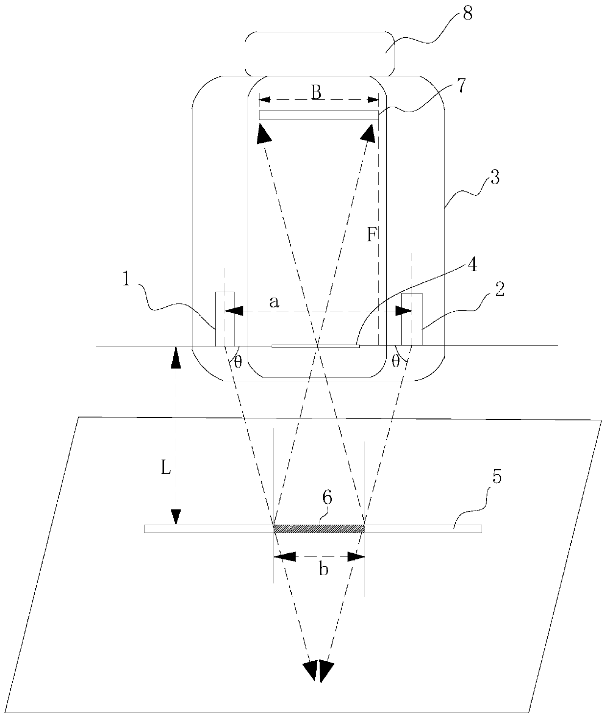
[0029] This embodiment provides a machine vision-based online detection method for flameproof joint surface gaps, such as figure 1 As shown, it is mainly used to detect the width of the gap to be measured, including the following steps:

[0030] S1. Set two sets of line light sources 1 and 2 above the gap 5 to be measured, each set of line light sources 1 and 2 are located on the same horizontal line, and the line beams emitted by each set of line light sources 1 and 2 have the same Angle θ; a convex lens 4 is arranged between the two groups of line light sources 1 and 2, and the center of the convex lens 4 is located on the same horizontal line as each group of line light sources 1 and 2; a CCD imaging module is arranged above the convex lens 4; Adjust the focal length F of the convex lens 4, so that the imaging of the gap 5 to be measured (in this embodiment, the gap between the flameproof joint surface of the explosion-proof electrical equipment) is in a clear state;

[00...

Embodiment 2

[0042] This embodiment provides a device for the method described in Embodiment 1, such as figure 1 As shown, it includes a line light source 1 and 2, a convex lens 4, a CCD imaging module, an image analysis calculation module and a power supply 8, and the power supply 8 supplies power for the line light source, the CCD imaging module and the image analysis calculation module;

[0043] The line light sources include two groups, each group of line light sources 1 and 2 are located on the same horizontal line, and the line beams emitted by each group of line light sources 1 and 2 have the same angle with the horizontal line; The gap to be measured emits a linear beam, which is on the same plane as the gap to be measured and intersects;

[0044] The convex lens 4 is arranged between the two groups of line light sources 1 and 2, and its center is on the same horizontal line as the line light source, so that the interval 6 between the incident points of the two groups of line light...


PUM


Abstract

The invention discloses an explosion-proof joint surface gap online detection method and device based on machine vision. On-line detection of an explosion-proof joint surface gap of coal mine explosion-proof electrical equipment is realized based on a linear light source structure and an amplification imaging module which form an angle with each other, an existing manual feeler gauge measurement method is replaced, and the innovation of on-line, real-time and accurate measurement of the explosion-proof gap is realized. Specifically, the ratio of the distance between the detection device and the surface of the explosion-proof gap to the focal length can be obtained in real time, the method serves as a method for calibrating the width of the explosion-proof gap in real time, a fixed clamp isnot used for measurement and sampling, constraints of the angle and the distance of the fixed clamp are eliminated, measurement can be conducted while calibration is conducted, and convenience and flexibility are achieved.

Description

technical field [0001] The invention relates to the field of flameproof joint surface parameters and machine vision gap detection of underground explosion-proof electrical equipment in coal mines, in particular to an online detection method and device for flameproof joint surface gaps based on machine vision. Background technique [0002] Flameproof equipment is the most widely used electrical equipment in coal mines, and its explosion-proof principle is based on the gap between flameproof joints. The gap width of the explosion-proof joint is an important work content of the explosion-proof inspection on the coal mine site. At present, the measurement of the joint surface gap of explosion-proof equipment adopts the method of manual screening with feeler gauge, the detection method is backward, and the accurate width information of the explosion-proof gap cannot be obtained in real time and online. Therefore, the study of a portable on-line detection technology and equipment...

Claims


Application Information

Patent Timeline
IPC IPC(8): G01B11/14
CPCG01B11/14
Inventor 张勇刘媛宁雅农刘统玉常琳甘波平金光贤董果凤
Owner 安标国家矿用产品安全标志中心有限公司
Features
  • R&D
  • Intellectual Property
  • Life Sciences
  • Materials
  • Tech Scout
  • Unparalleled Data Quality
  • Higher Quality Content
  • 60% Fewer Hallucinations
Learn More