Conveying device and conveying system

A delivery device and housing technology, applied in stents, trocars, heart valves, etc., can solve the problems of high intracavity pressure, adverse consequences, and unsatisfactory release positions of artificial valves, and achieve accurate and reliable release positions and reduce risks. Effect

Active Publication Date: 2020-06-30
LIFETECH SCIENTIFIC (SHENZHEN) CO LTD
View PDF17 Cites 4 Cited by
  • Summary
  • Abstract
  • Description
  • Claims
  • Application Information

AI Technical Summary

Problems solved by technology

[0004] Although transcatheter intervention to replace the natural mitral valve is an effective method for treating mitral valve insufficiency, the release position of the artificial valve may Unsatis

Method used


Image

  • Conveying device and conveying system
  • Conveying device and conveying system
  • Conveying device and conveying system

Examples


Embodiment 1

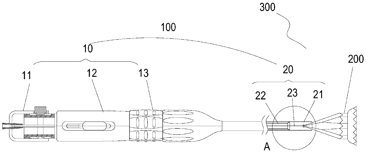
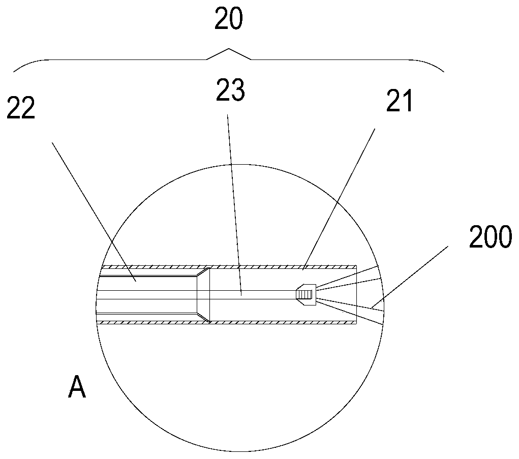
[0028] Such as figure 1 As shown, the delivery device 100 of this embodiment includes a control assembly 10 and a catheter assembly 20 . The control assembly 10 is connected to the proximal end of the catheter assembly 20 for controlling the movement of the catheter assembly 20 . The control assembly 10 includes a first control mechanism 11 , a second control mechanism 12 and a third control mechanism 13 . Wherein, the second control mechanism 12 is arranged between the first control mechanism 11 and the third control mechanism 13, the first control mechanism 11 is arranged near the proximal end of the control assembly 10, and the third control mechanism 13 is arranged near the far end of the control assembly 10 . Also refer to figure 2 , the catheter assembly 20 includes an outer tube 21 , a middle tube 22 and an inner tube 23 . The distal end of the inner tube 23 is provided with a threaded structure for connecting with the implant; the middle tube 22 is sleeved outside...

Embodiment 2

[0040] The structure of the conveying device in this embodiment is basically the same as that of the conveying device 100 in Embodiment 1, except for the first control mechanism 31 . Such as Figure 7 As shown, the first control mechanism 31 of this embodiment includes a housing 34 , a receiving part 352 and a limiting part 351 . The structure of the housing 34 in this embodiment is basically the same as that of the housing 14 in the first embodiment, and will not be repeated here. The receiving part 352 is provided with an axial groove 353 and a circumferential groove 354, and the circumferential groove 354 is close to the proximal end of the axial groove 353, and the two are not connected. Such as Figure 8 As shown, the limiting member 351 includes a pressing plate 358 and a second stop body 357 and a third stop body 359 disposed inside the press plate 358 . Wherein the second stop body 357 is close to the distal end of the pressing plate 358 , and the third stop body 35...


PUM


Abstract

The invention discloses a conveying device which comprises a guide tube assembly and a control assembly, wherein the control assembly is arranged at the rear end of the guide tube assembly; the control assembly comprises a first control mechanism; the first control mechanism comprises a hollow shell and a limiting unit; the limiting unit comprises a limiting part and a hollow accommodation part; the accommodation part is arranged in the shell; an axial groove and a circumferential groove are formed in the outer surface of the accommodation part; the limiting part penetrates through the shell and is accommodated in the axial groove or the circumferential groove, and then the shell can be axially moved or circumferentially rotated; and the limiting part is further driven by the shell to moveaxially or rotate circumferentially. By adopting the conveying device and a conveying system disclosed by the invention, a first control part is arranged, and a connecting guide tube in the guide tube assembly connected with an implant can be directly controlled to be rapidly switched to circumferential movement from axial movement, so that accurate and reliable implant release positions can be achieved, the implant can be tightly adhered to tissue, and the risk of perivalvular leakage can be reduced.

Description

technical field [0001] The invention relates to the field of interventional medicine, in particular to a delivery device and a delivery system. Background technique [0002] The human heart is divided into four chambers, each with its own "outlet," and a total of four valves (mitral, aortic, pulmonary, and tricuspid) that ensure the Blood can flow in the designated direction in the cardiovascular system. The mitral valve is located between the left atrium and the left ventricle. The normal mitral valve ensures blood circulation from the left atrium to the left ventricle and prevents blood from flowing back from the left ventricle of the heart to the left atrium. The occurrence of various heart diseases or degenerative diseases may lead to mitral valve dysfunction, making the mitral valve become abnormally narrowed or dilated. The loss of mitral valve function will affect the normal work of the heart, resulting in gradual weakness or life-threatening. [0003] Aiming at th...

Claims


Application Information

Patent Timeline
IPC IPC(8): A61F2/95
CPCA61F2/95A61B17/34A61F2/24A61F2/966
Inventor 江巍彭峰
Owner LIFETECH SCIENTIFIC (SHENZHEN) CO LTD
Why Eureka
Try Eureka