
Spraying system for plant protection unmanned aerial vehicle and switching method thereof

A plant protection UAV and spraying system technology, applied in the spraying system of plant protection UAV and its switching field, can solve the problems of heavy weight, reduce the single use time of plant protection UAV, increase the load weight of plant protection UAV, etc.

Pending Publication Date: 2020-06-30
南京诚朴无人机有限公司
View PDF3 Cites 1 Cited by
  • Summary
  • Abstract
  • Description
  • Claims
  • Application Information

AI Technical Summary

Problems solved by technology

[0002] When the plant protection UAV is working outdoors, the traditional pesticide spraying mode is a combination of a water pump and four nozzles. Among them, the four nozzles are two in the front and two in the back. However, when the four nozzles are turned on at the same time, it will cause Pesticides adhere to the surface of the drone and affect the spraying effect
The existing solution is to open the rear nozzle when the UAV is flying forward, and open the front nozzle when the UAV is flying backward. Although the problem of sprayed pesticides adhering to the surface of the UAV is solved to a certain extent, However, to realize this function currently requires two sets of spraying systems to work together, that is, two water pumps are required, but the weight of the water pump is relatively large, about one kilogram, which increases the load weight of the plant protection drone during operation and reduces the weight of the plant protection drone. The single use time is long, so there is an urgent need for a convenient and lightweight plant protection drone spraying system and its switching method to solve this problem

Method used


Image

  • Spraying system for plant protection unmanned aerial vehicle and switching method thereof

Examples


Embodiment 1

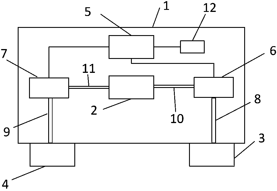
[0013] like figure 1 As shown, a spraying system for plant protection UAV:

[0014] It includes plant protection UAV frame 1, water pump 2, nozzle group A3, nozzle group B4, central control module 5, solenoid valve A6, solenoid valve B7, water outlet pipe A8, water outlet pipe B9, water inlet pipe A10, water inlet pipe B11 and Pose sensor 12; wherein, the water pump 2 is placed inside the frame 1 of the plant protection drone, the nozzle group A3 is placed at the front of the frame 1 of the plant protection drone, the nozzle group A3 is connected to the outlet pipe A8, and the outlet pipe A8 is connected to the solenoid valve One side of A6, the other side of the solenoid valve A6 is connected to the water inlet pipe A10, the water inlet pipe A10 is connected to the water pump 2, the solenoid valve A6 is connected to the central control module 5, and the nozzle group B4 is placed at the rear of the plant protection drone frame 1. Group B4 is connected to the outlet pipe B9, t...


PUM


Abstract

The invention discloses a spraying system for a plant protection unmanned aerial vehicle and a switching method thereof. The spraying system comprises a plant protection unmanned aerial vehicle frame,a water pump, a nozzle group A, a nozzle group B, a central control module, an electromagnetic valve A, an electromagnetic valve B, a water outlet pipe A, a water outlet pipe B, a water inlet pipe A,a water inlet pipe B and a pose sensor. The flight direction of the plant protection unmanned aerial vehicle is detected through the pose sensor; when the plant protection unmanned aerial vehicle isdetected to fly forwards, the electromagnetic valve B arranged at the rear part of the rack is opened through the central control module and the electromagnetic valve A arranged at the front part of the rack is closed, so that the water pump opens a rear water path to spray pesticide; when the plant protection unmanned aerial vehicle is detected to fly backwards, the electromagnetic valve A arranged on the front portion of the rack is opened and the electromagnetic valve B arranged on the rear portion of the rack is closed through the central control module, so that the water pump opens a front water way to spray pesticide. Therefore, the pesticide sprayed out is sprayed to the rear portion of the flying direction of the plant protection unmanned aerial vehicle when only one water pump isused and cannot be sprayed to the plant protection unmanned aerial vehicle.

Description

technical field [0001] The invention relates to the technical field of unmanned aerial vehicles, in particular to a spraying system for plant protection drones and a switching method thereof. Background technique [0002] When the plant protection UAV is working outdoors, the traditional pesticide spraying mode is a combination of a water pump and four nozzles. Among them, the four nozzles are two in the front and two in the back. However, when the four nozzles are turned on at the same time, it will cause Pesticides adhere to the surface of the drone and affect the spraying effect. The existing solution is to open the rear nozzle when the UAV is flying forward, and open the front nozzle when the UAV is flying backward. Although the problem of sprayed pesticides adhering to the surface of the UAV is solved to a certain extent, However, to realize this function currently requires two sets of spraying systems to work together, that is, two water pumps are required, but the we...

Claims


Application Information

Patent Timeline
IPC IPC(8): B64D1/18B64C39/02
CPCB64D1/18B64C39/02B64U2101/00
Inventor 邓海啸
Owner 南京诚朴无人机有限公司
Learn More