Drainage system and drainage method based on municipal road separate pipe network
A technology for municipal roads and drainage systems, applied in waterway systems, sewer systems, water supply devices, etc., can solve problems such as waste of resources, pollution, and pollution of receiving water bodies, and achieve low transformation costs, diverse applicable environments, and avoid mixing Effect
- Summary
- Abstract
- Description
- Claims
- Application Information
AI Technical Summary
Problems solved by technology
Method used
Image
Examples
Embodiment 1
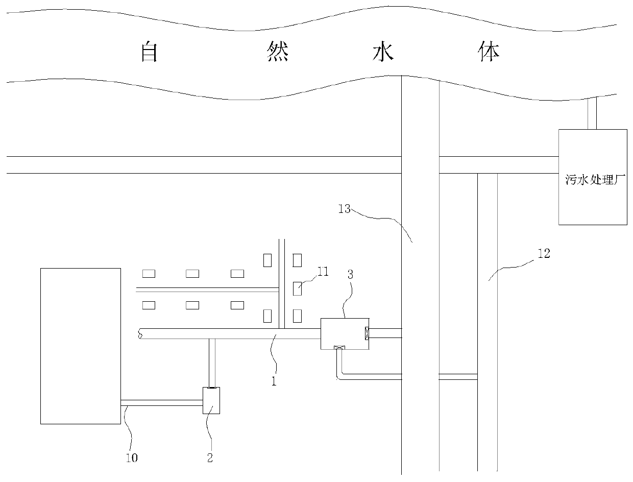
[0039] see figure 1 As shown, the existing combined pipe network system has a sewage branch pipe 10, a rainwater outlet 11 and a combined pipe 1 located in the unit area. The water flowing out of the unit area enters the municipal sewage pipe 12 and the municipal rainwater pipe 13. The sewage branch pipe in the unit area 10 and rainwater outlet 11 are respectively connected along the line of the confluence pipe 1, and the sewage branch pipe 10 and rainwater outlet 11 are connected in parallel along the line of the confluence pipe 1; the unit areas in the present embodiment are districts, hospitals, office buildings and other areas.
[0040] This embodiment provides a drainage system based on municipal road diversion pipe network, which is based on the transformation of the existing combined pipe network system. The system includes:
[0041] The intercepting part 2 is arranged near the access part where the sewage branch pipe 10 is connected to the confluence pipe 1 or upstream...
Embodiment 2
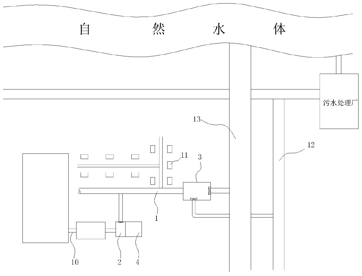
[0044] see figure 2 As shown, the existing combined pipe network system has a sewage branch pipe 10, a rainwater outlet 11, a sewage storage facility (such as a septic tank) and a combined pipe 1 located in the unit area, and a septic tank outlet and a rainwater outlet 11 in the unit area. They are respectively connected along the line of the confluence pipe 1, and the septic tank and the rainwater outlet 11 are connected in parallel along the line of the confluence pipe 1; the unit areas in this embodiment are districts, hospitals, office buildings and other areas.
[0045] The difference between this embodiment 2 and embodiment 1 is:
[0046] The intercepting part 2 in the embodiment 1 is arranged between the sewage branch pipe 10 and the confluence pipe 1 or the connecting part between the sewage branch pipe and the confluence pipe 1;
[0047] The intercepting part 2 in the embodiment 2 is arranged between the outlet of the septic tank and the confluence pipe 1 or at the ...
Embodiment 3
[0049] see figure 1 and figure 2 As shown, on the basis of Embodiment 1 and Embodiment 2, for the arrangement of sewage branch pipes, interceptors and sewage storage facilities:
[0050] Mode 1, the number of the sewage branch pipe is one, the number of the intercepting part 2 is one, and one sewage storage facility is arranged between one sewage branch pipe 10 and one intercepting part 2, The inlet of one intercepting part 2 is connected with the outlet of one sewage storage facility;
[0051] Mode 2, the number of the sewage branch pipes 10 is several, the number of the intercepting parts 2 and the number of the sewage storage facilities are all adapted to the number of the sewage branch pipes 10, and each of the sewage branch pipes 10 A corresponding sewage storage facility is arranged between the corresponding one of the intercepting parts 2, and the inlet of each of the intercepting parts 2 is connected to the outlet of the corresponding one of the sewage storage facil...
PUM
 Abstract
Description
Claims
Application Information
 - R&D
- Intellectual Property
- Life Sciences
- Materials
- Tech Scout
- Unparalleled Data Quality
- Higher Quality Content
- 60% Fewer Hallucinations
Browse by: Latest US Patents, China's latest patents, Technical Efficacy Thesaurus, Application Domain, Technology Topic, Popular Technical Reports.
© 2025 PatSnap. All rights reserved.Legal|Privacy policy|Modern Slavery Act Transparency Statement|Sitemap|About US| Contact US: help@patsnap.com


