
A seed metering mechanism for directional seeding and a secondary suppression seeder

A technology for seeding mechanism and seeder, which is applied to the parts of seeder, sowing seeder, sowing, etc., can solve the problems of inconsistent peanut emergence time, loose soil, inconsistent germ orientation, etc.

Active Publication Date: 2021-05-25
SHANDONG ACADEMY OF AGRICULTURAL MACHINERY SCIENCES
View PDF10 Cites 0 Cited by
  • Summary
  • Abstract
  • Description
  • Claims
  • Application Information

AI Technical Summary

Problems solved by technology

[0006] The purpose of the present invention is to provide a kind of seeding mechanism for directional planting and a secondary suppression seeder, which can solve the problem of soil loosening and poor contact between peanut seeds and soil caused by rotary tillage machines in existing peanut sowing; When the germs fall into the seed ditch, the orientation of the germs is inconsistent, resulting in inconsistent emergence time of peanuts

Method used


Image

  • A seed metering mechanism for directional seeding and a secondary suppression seeder
  • A seed metering mechanism for directional seeding and a secondary suppression seeder
  • A seed metering mechanism for directional seeding and a secondary suppression seeder

Examples


Embodiment 1

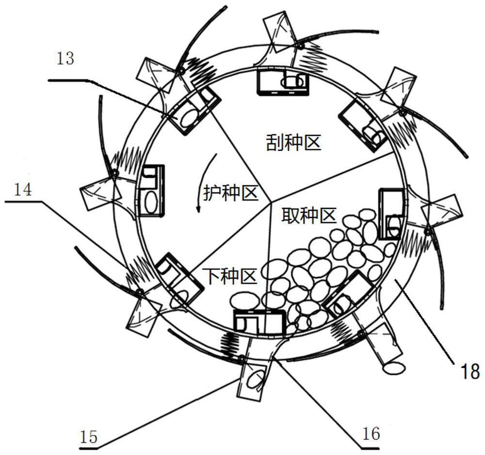
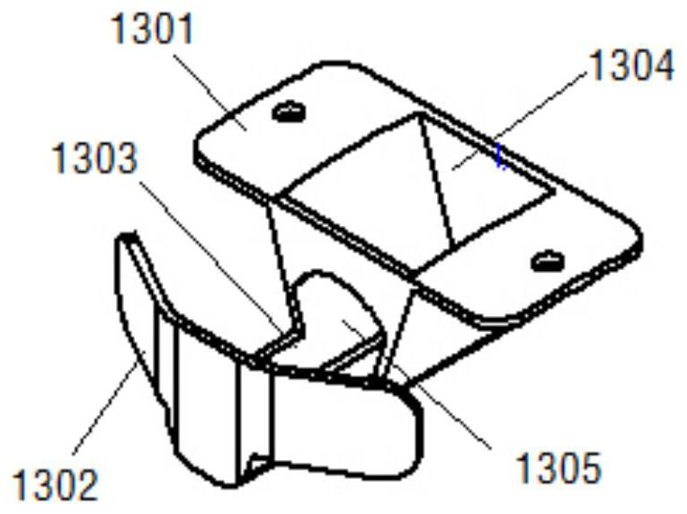
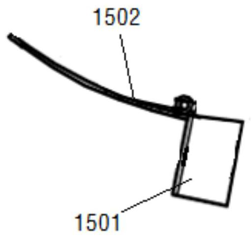
[0033] Such as Figure 1-5 As shown, the present embodiment provides a kind of directional seeding mechanism (the seeding mechanism here can be referred to as a seed meter again), including a sowing circle 18, and the two ends of the sowing circle pass through the end plate (Fig. (not shown) closed, the side wall of the sowing ring is evenly distributed with a plurality of through holes along the circumferential direction; each through hole is respectively fixed with a fixed duckbill 16 with an inner channel, the fixed duckbill One end of 16 protrudes into the through hole, and the other end protrudes away from the through hole.

[0034] It should be pointed out that although the two ends of the sowing circle are closed by end plates, a seed inlet should be provided at one of the end plates, and the seed inlet should be connected with the upper seed box through a pipe, so that the seed box can flow toward the sowing circle. Seeds are provided in the inner cavity, and the spec...

Embodiment 2

[0049] Such as Figure 6-8 As shown, the present embodiment provides a secondary suppression seeder, including a frame 1, and the bottom of the frame 1 is sequentially equipped with a ridging shovel 2, a seeding mechanism 4, a film covering mechanism, and a soil covering mechanism on the film. The lower part of the frame 1 is also equipped with a primary pressing roller 3 and a secondary pressing wheel 10 that can rotate along its own axis respectively; The roller 3 includes a roller body 32, and at least one annular boss 33 is provided on the outer circular side of the roller body 32, and the annular boss 33 can extrude a seed ditch on the upper surface of the field ridge.

[0050] The primary pressing roller 3 can utilize itself and the gravity of the frame 1 to squeeze the field ridge during the movement of the random frame 1, so as to realize the compaction and compaction of the field ridge before sowing; the secondary pressing wheel 10 is installed on the The soil coveri...


PUM


Abstract

The invention relates to a seeding mechanism for directional planting and a secondary suppression seeder, comprising a sowing circle, the two ends of the sowing circle are closed by end plates, and the side walls of the sowing circle are evenly distributed along the circumferential direction with multiple holes. a through hole; each through hole is respectively fixed with a fixed duckbill with an inner channel, one end of the fixed duckbill stretches into the through hole, and the other end stretches out toward the direction away from the through hole; each fixed duckbill There is a movable duckbill connected to the mouth in rotation, and a spring is installed between the movable duckbill and the outer wall of the sowing ring. The movable duckbill can realize the opening and closing conversion of the inner channel away from the end of the inner cavity of the sowing ring during the rotation process. There is a slide plate in the fixed duckbill, and the slide plate is used to transport seeds, and the extension curve of the slide plate is set so that when the seeds fall from the end of the slide plate away from the sowing ring, the seeds are in a horizontal state.

Description

technical field [0001] The invention belongs to the technical field of agricultural machinery, and in particular relates to a seed metering mechanism for directional seeding and a secondary suppression seeder. Background technique [0002] "Full seedlings, uniform seedlings, uniform seedlings, and strong seedlings" are the prerequisites for high peanut yield. At present, peanut planters usually use double-disc ditching devices to open seed furrows, and then use slot wheels or air-suction seed metering devices. The seeds are discharged, and finally the seeds fall into the seed ditch through the seed guide tube. In the process of agricultural production, the sowing process of some other crops is similar to that of peanuts, and the description below will only take peanuts as an example. [0003] The inventor has learned that the soil before sowing peanuts will be sorted with a rotary tiller to loosen the soil and increase air permeability. However, this soil preparation metho...

Claims


Application Information

Patent Timeline
Patent Type & Authority Patents(China)
IPC IPC(8): A01B49/02A01B49/04A01B49/06A01C5/06A01C7/16A01C7/20A01G13/02
CPCA01B49/022A01B49/027A01B49/04A01B49/065A01C5/064A01C7/166A01C7/20A01G13/0287
Inventor 万书波张佳蕾康建明张宁宁彭强吉张春艳郭峰
Owner SHANDONG ACADEMY OF AGRICULTURAL MACHINERY SCIENCES
Learn More