Fire hose cleaning device

A technology of cleaning device and fire hose, applied in fire rescue and other directions, can solve the problems of easy residual water stains, heavy labor, affecting use, etc., to improve cleaning efficiency and cleaning quality, facilitate feeding operations, and improve cleaning quality. Effect

Active Publication Date: 2020-07-03
邳州市景鹏创业投资有限公司
View PDF12 Cites 1 Cited by
  • Summary
  • Abstract
  • Description
  • Claims
  • Application Information

AI Technical Summary

Problems solved by technology

[0004] Based on the technical problems of mainly relying on firefighters to clean in the pool, the labor load is large, and water stains are easy to remain inside during the cleaning process, which affects the later use, the present invention proposes a fire hose cleaning device

Method used


Image

  • Fire hose cleaning device
  • Fire hose cleaning device
  • Fire hose cleaning device

Examples


Embodiment 1

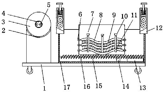
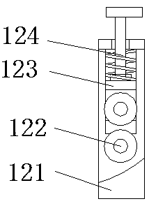
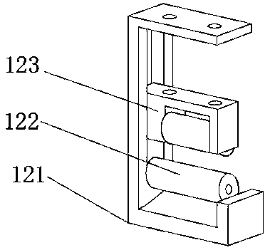
[0028] refer to Figure 1-4 , a fire hose cleaning device, comprising a base 1, a cleaning box 17 is fixedly installed on one side of the top of the base 1, and a support frame 3 is fixedly installed on the other side of the top of the base 1, and a side bottom of the cleaning box 17 is fixedly installed with Sewage sealing plate 13 and drainpipe 14, the side of support frame 3 is fixedly installed with driving motor, and the output shaft of driving motor is fixedly installed with winding mechanism, and the top both sides of cleaning box 17 is all fixedly installed with guiding mechanism 12, and cleaning The top of the box 17 is hinged with a mounting frame 7 of L-shaped structure, and the side of the mounting frame 7 is fixedly equipped with three cleaning plates 8 of wave-shaped structure, and the sides of the three cleaning plates 8 are fixedly equipped with a plurality of cleaning brushes. 9. Three limit mechanisms are fixedly installed on the side of the installation fram...

Embodiment 2

[0039] refer to Figure 1-3 and Figure 5 , a fire hose cleaning device. Compared with Embodiment 1, this embodiment also includes: an auxiliary frame 18 fixedly installed on the side of the mounting frame 7, and the bottom ends of the mounting frame 7 and the auxiliary frame 18 are fixedly installed with a row of Springs 20, the bottom end of each row of springs 20 is fixedly equipped with a support plate 21, and the tops of the auxiliary frame 18 and the mounting frame 7 are fixedly equipped with a vibration motor 19.

[0040] In this embodiment: during the cleaning process, the installation frame 7 is fixed on the top of the cleaning box 17 through the two support plates 21 at the bottom, the vibration motor 19 is turned on during the cleaning process, and the cleaning plate 8 is driven to vibrate, and then the cleaning brush 9 is used to Through the fire hose for effective cleaning, improve cleaning efficiency and cleaning quality.


PUM


Abstract

The invention belongs to the technical field of fire fighting, particularly relates to a fire hose cleaning device. The fire hose cleaning device solves the problems that a fire hose is mainly reliedon cleaning in a water pool by firemen, the labor amount is large, water stains are prone to remaining in the cleaning process, and later use is affected. According to the technical scheme, the fire hose cleaning device comprises a base, wherein a cleaning box is fixedly installed on one side of the top of the base, a supporting frame is fixedly installed on the other side of the top of the base,a pollution discharge sealing plate and a drainage pipe are fixedly installed at the bottom of the side face of the cleaning box, and a driving motor is fixedly installed on the side face of the supporting frame. According to the fire hose cleaning device, the driving motor drives the folding position of the fire hose to be wound and pulls the fire hose to pass among three cleaning plates, the fire hose is comprehensively cleaned through the concave-convex fluctuation characteristic of the cleaning plates of a wavy structure, the side faces of the cleaning plates are in an exposed state, the bottom end of a mounting frame can be lifted away from the interior of the cleaning box, feeding operation is facilitated, falling garbage can be conveniently brushed and discharged, and the cleaning quality is improved.

Description

technical field [0001] The invention relates to the technical field of fire protection, in particular to a fire hose cleaning device. Background technique [0002] "Fire" is to eliminate hidden dangers and prevent disasters (that is, the general term for preventing and solving the man-made, natural and accidental disasters that people encounter in the process of life, work and study). Of course, the narrow meaning is: (extinguishing) The fire means that the fire hose is a hose used to transport high-pressure water or foam and other flame-retardant liquids during a fire. A traditional fire hose is lined with rubber and wrapped with a linen braid on the outside. Advanced fire hoses are made of polymeric materials such as polyurethane. Both ends of the fire hose have metal connectors that can be connected to another hose to extend the distance or to a nozzle to increase the pressure of the liquid spray. [0003] In the fire station, it is often necessary to carry out fire dr...

Claims


Application Information

Patent Timeline
IPC IPC(8): A62C33/02
CPCA62C33/02
Inventor 王聪燕
Owner 邳州市景鹏创业投资有限公司
Why Eureka
Try Eureka