
Working method of machining device for annular metal parts

A technology for metal parts and processing devices, applied in the field of mechanical processing equipment, can solve the problems of thin annular workpiece processing, low applicability and other problems, and achieve the effects of solving workpiece deformation, improving practicability and reducing costs

Active Publication Date: 2020-07-03
唐山特迪机械设备制造有限公司
View PDF16 Cites 2 Cited by
  • Summary
  • Abstract
  • Description
  • Claims
  • Application Information

AI Technical Summary

Problems solved by technology

[0004] The purpose of the present invention is to provide a processing device for ring-shaped metal parts to solve the technical problems of low applicability and inability to process thin ring-shaped workpieces in the prior art

Method used


Image

  • Working method of machining device for annular metal parts
  • Working method of machining device for annular metal parts
  • Working method of machining device for annular metal parts

Examples


Embodiment Construction

[0029] The technical solutions of the present invention will be clearly and completely described below in conjunction with the accompanying drawings. Apparently, the described embodiments are some of the embodiments of the present invention, but not all of them.

[0030] The components of the embodiments of the invention generally described and shown in the figures herein may be arranged and designed in a variety of different configurations. Accordingly, the following detailed description of the embodiments of the invention provided in the accompanying drawings is not intended to limit the scope of the claimed invention, but merely represents selected embodiments of the invention.

[0031] Based on the embodiments of the present invention, all other embodiments obtained by persons of ordinary skill in the art without making creative efforts belong to the protection scope of the present invention.

[0032] In the description of the present invention, it should be noted that the...


PUM


Abstract

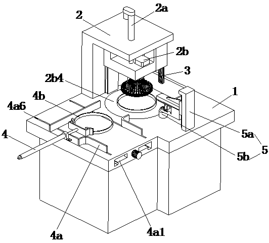
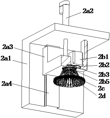
The invention discloses a working method of a machining device for annular metal parts, and belongs to the technical field of machining equipment. The machining device comprises a workbench, a positioning mechanism, a limiting mechanism, a feeding mechanism and a polishing mechanism. The positioning mechanism comprises a lifting assembly, a connecting assembly, a plurality of positioning assemblies and a plurality of reset assemblies. The connecting assembly is installed at the lower end of the lifting assembly. The plurality of positioning assemblies are circumferentially distributed beside the connecting assembly. The plurality of reset assemblies correspond to the plurality of positioning assemblies one to one. Each reset assembly is installed above the corresponding positioning assembly. The feeding mechanism comprises an adjusting assembly and a feeding assembly, and the polishing mechanism comprises a moving assembly and a polishing assembly. According to the working method, annular workpieces with small inner and outer diameter difference values can be fixed and machined, workpiece deformation cannot be caused during fixing, and the same equipment can machine the annular workpieces of different sizes. The machining device further has the advantage of low positioning precision, and the cost can be reduced.

Description

technical field [0001] The invention relates to the technical field of mechanical processing equipment, in particular to a working method of a processing device for ring metal parts. Background technique [0002] Ring metal parts are commonly used workpieces. After processing and production, due to burrs and other phenomena on the surface, they need to be polished before they can be used. With the development of industry, the current ring metal parts are all mechanically polished. [0003] Chinese Patent No. CN107263253B discloses a ring-shaped workpiece grinding device, including a base frame and a fixed frame arranged on the bottom frame, and a slide groove is also arranged on the left side of the fixed frame on the bottom frame, so that A sliding frame that can slide left and right is provided in the sliding groove, and an upper-passing groove is arranged on the top of the sliding frame, and a horizontal frame is slidably arranged in the upper-passing groove, and the ri...

Claims


Application Information

Patent Timeline
Patent Type & Authority Applications(China)
IPC IPC(8): B24B9/04B24B29/02B24B41/00B24B41/06B24B47/12
CPCB24B9/04B24B29/02B24B41/005B24B41/06B24B47/12
Inventor 张卓群
Owner 唐山特迪机械设备制造有限公司
Learn More