
Air seal mechanism for front end of main shaft

A technology of spindle front end and air seal, which is applied in the direction of engine sealing, mechanical equipment, engine components, etc., and can solve the problems of the spindle's waterproofness and airtightness reduction.

Pending Publication Date: 2020-07-03
深圳市爱贝科精密工业股份有限公司
View PDF0 Cites 4 Cited by
  • Summary
  • Abstract
  • Description
  • Claims
  • Application Information

AI Technical Summary

Problems solved by technology

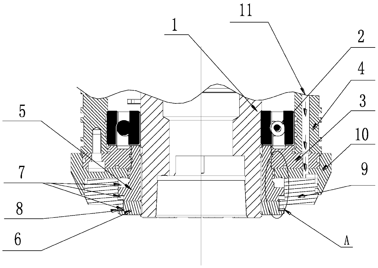
[0004] Aiming at the deficiencies of the prior art, the present invention provides an air seal mechanism for the front end of the main shaft. The front end of the ring spray plate is provided with a sealing structure formed by a radial step and a waterproof cover to prevent water splashing on the nose of the main shaft. When flowing downward by gravity, it will stop at the step and will not enter the air seal to prevent possible negative pressure inside the main shaft from causing inhalation. In addition, the maximum outer circle of the radial step and the outer circle of the waterproof cover are equal in size or the outer circle of the waterproof cover It is slightly smaller to reduce the accumulation on the air cover and affect the sealing effect. At the same time, a water suction groove is added near the bearing end; it solves the problem of the water resistance and sealing performance of the spindle after long-term use. At the beginning of the air pressure, due to Negative pressure, causing moisture from the compressed air to enter the bearing

Method used


Image

  • Air seal mechanism for front end of main shaft
  • Air seal mechanism for front end of main shaft

Examples


Embodiment Construction

[0025] The following will clearly and completely describe the technical solutions in the embodiments of the present invention with reference to the accompanying drawings in the embodiments of the present invention. Obviously, the described embodiments are only some, not all, embodiments of the present invention. Based on the embodiments of the present invention, all other embodiments obtained by persons of ordinary skill in the art without making creative efforts belong to the protection scope of the present invention.

[0026] see Figure 1-2 , an air seal mechanism for the front end of the main shaft, including a rotor 1, a dust cover 5 is arranged outside the rotor 1, a waterproof cover 6 is fixed on the front end of the dust cover 5, and the rear end of the dust cover 5 is in conflict with the bearing 2, The outer ring of the bearing 2 is provided with a bearing seat, and the front end of the bearing 2 is offset against the bearing pressure 3, and the front end of the bear...


PUM


Abstract

The invention relates to the technical field of main shafts, and discloses an air seal mechanism for the front end of a main shaft. The air seal mechanism comprises a rotor, wherein a dustproof coveris arranged outside the rotor, a waterproof cover is fixed at the front end of the dustproof cover, the rear end of the dustproof cover abuts against a bearing, a bearing seat is arranged on the outerring of the bearing, the front end of the bearing abuts against a bearing pressing plate, the front end of the bearing pressing plate is provided with the dustproof cover, the dustproof cover abuts against an annular spraying plate, the dustproof cover and the annular spraying plate form annular air bags, and the front end of the dustproof cover abuts against the waterproof cover and forms an annular L-shaped gap; when the main shaft is inflated, the compressed air enters the air bags and is at a high pressure, the air bags are at a low pressure, the air flows to the air bags, then the compressed air of the air bags is discharged outside due to the low pressure outside, when the main shaft runs at a high speed, the generated centrifugal pump pressure is outside, the situation that due tothe negative pressure pumped inwards by a centrifugal pump, external cooling water is sucked into the main shaft is effectively prevented, the air seal protection at the front end of the main shaft iseffectively improved, and compared with other modes, the waterproof effect is superior.

Description

technical field [0001] The invention relates to the technical field of spindles, in particular to an air seal mechanism for the front end of a spindle. Background technique [0002] Most of the traditional machine tool spindle seals adopt a labyrinth seal structure, with only a single static seal ring, which is far from meeting the processing needs of grinding machine tools, especially on high-pressure, large-flow powerful forming grinding machines. The traditional structure will lead to short service life of rolling bearings, lower equipment accuracy, affect the normal operation and durability of the machine tool, thereby reducing the waterproof and sealing performance of the spindle, and affect the use of the spindle. Contents of the invention [0003] (1) Solved technical problems [0004] Aiming at the deficiencies of the prior art, the present invention provides an air seal mechanism for the front end of the main shaft. The front end of the ring spray plate is provid...

Claims


Application Information

Patent Timeline
Patent Type & Authority Applications(China)
IPC IPC(8): B24B41/04F16J15/40
CPCB24B41/04F16J15/40
Inventor 农乃昌
Owner 深圳市爱贝科精密工业股份有限公司
Learn More