Prefabricated box girder end die capable of being rapidly positioned and dismounted

An end-die and fast technology, applied in the direction of molds, manufacturing tools, mold trays, etc., can solve the problems of slow speed, affecting the quality of the beam body, and difficulty in dismantling.

Pending Publication Date: 2020-07-03
NO 1 ENG CO LTD OF CR11BG +2
View PDF0 Cites 4 Cited by
  • Summary
  • Abstract
  • Description
  • Claims
  • Application Information

AI Technical Summary

Problems solved by technology

[0003] The purpose of the present invention is to provide a prefabricated box girder end form that can be quickly positioned and removed in view of the current prefabricated girder box end formwork that is difficult to locate and dismantle and is slow in speed, easily damages the concre...

Method used


Image

  • Prefabricated box girder end die capable of being rapidly positioned and dismounted
  • Prefabricated box girder end die capable of being rapidly positioned and dismounted
  • Prefabricated box girder end die capable of being rapidly positioned and dismounted

Examples


Embodiment Construction

[0019] specific implementation plan

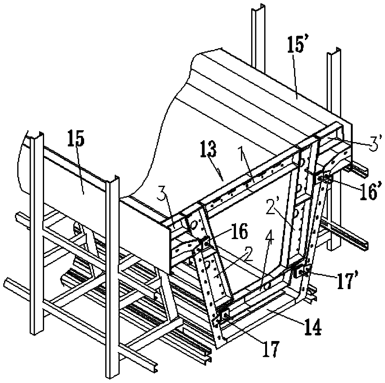
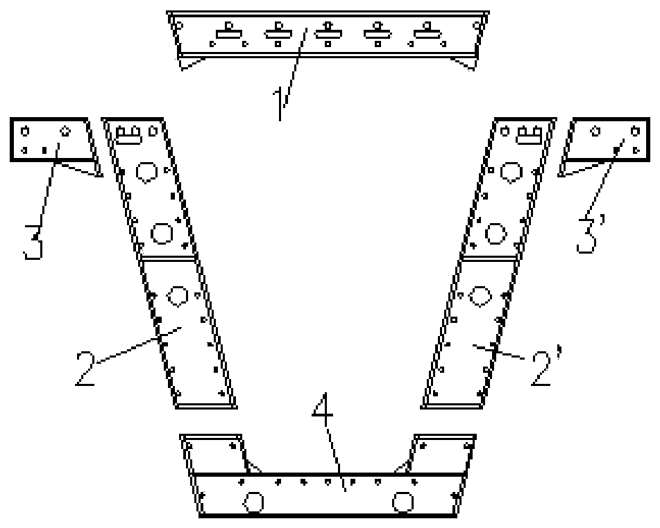
[0020] given by the present invention figure 1 , figure 2 , image 3 and Figure 4 In the embodiment, a prefabricated box girder end form that can be quickly positioned and removed is processed into an end form (integral) 13 with section steel, and the end form 13 is composed of a top plate 1, a left web 2, a right web 2', and a left flange 3 , the right flange plate 3', the bottom plate 4, and the comb plate 5; the two ends of the top plate 1 are respectively welded on the inner side of the upper end of the left web 2 and the right web 2', and are connected with the left web 2 and the right web 2 The upper ends are flush with each other; the left flange plate 3 and the right flange plate 3’ are respectively welded on the outer sides of the upper ends of the left web plate 2 and the right web plate 2’, and the left flange plate 3 and the right flange plate 3’ are connected to the upper top plate 1. Flat; the bottom plate 4 is welded a...


PUM


Abstract

The invention provides a prefabricated box girder end die capable of being rapidly positioned and dismounted. The prefabricated box girder end die is characterized in that two end heads of a top plateare welded to inner sides of upper ends of a left web and a right web respectively; a left flange plate and a right flange plate are welded to outer sides of upper ends of the left web and the rightweb respectively and are flush with the upper top plate respectively; a bottom plate is welded at lower end heads of the left web and the right web, and a whole end die is formed accordingly; a comb plate is welded to the upper end of a bottom die; after a left side lateral die, a right side lateral die and the bottom die are mounted on a prefabricated beam pedestal respectively, girder steel barsare bound and prestressed pipes are mounted; front end heads of drawing screws of a first positioning device, a second positioning device, a third positioning device and a fourth positioning device with the same structure are welded to upper parts of the left web and the right web of the end die and left and right sides of the bottom plate respectively; and the whole end die is placed between theleft side lateral die and the right side lateral die, the bottom is aligned to the comb plate on the bottom die, the end die is controlled to move forwards by tightly screwing positioning screw caps,and accurate positioning and fixation of the end die are realized.

Description

technical field [0001] The invention relates to the technical field of bridge prefabricated box girder construction, in particular to a prefabricated box girder end form that can be quickly positioned and removed. Background technique [0002] The length of the prefabricated box girder is usually about 25-40m. The side formwork is composed of several sections of 5-6m. The end formwork needs to be set to an irregular shape according to the section form of the end of the box girder. Usually, the end formwork is embedded in the middle of the side formwork and the bottom formwork. to increase stability. After the concrete pouring of the beam body is completed, before the side formwork and inner formwork are removed, the end formwork embedded in the side formwork and bottom formwork needs to be removed first. Since the end formwork is embedded inside the side formwork and bottom formwork, manual use of crowbars and sledgehammers is required It is not only difficult to remove by ...

Claims


Application Information

Patent Timeline
IPC IPC(8): B28B7/00
CPCB28B7/0002B28B7/0014B28B7/0029B28B7/0055
Inventor 张耀蒋光森徐章超刘勇建张彬刘旭东乜颜君刘俊伟
Owner NO 1 ENG CO LTD OF CR11BG
Why Eureka
Try Eureka