
A ceramic inkjet printer ink path system

A ceramic inkjet and printer technology, applied in printing and other directions, can solve the problems of incomplete utilization of the ink circuit system, increase the risk of the whole machine, increase the number of pipeline parts, etc., to improve the ability to work continuously and stably for a long time, reduce gas Source processing device and proportional valve, reducing the effect of pressure instability

Active Publication Date: 2021-03-19
KEDA INDUSTRIAL GROUP CO LTD
View PDF11 Cites 0 Cited by
  • Summary
  • Abstract
  • Description
  • Claims
  • Application Information

AI Technical Summary

Problems solved by technology

[0003] 1. The existing ink system is independently controlled according to the needs of the nozzle, one ink box for entering and one for exiting the ink box, so it needs 2 sets of ink supply systems, 2 sets of air system and 2 sets of control systems to control the entry and exit of two ink cartridges, so The required parts and materials are very large, and the final cost is high, resulting in low market competitiveness;
[0004] 2. Now the ink system needs to have stirring motors, heating rods, heating strips and other materials, which will increase the risk of the whole machine, control points and costs;
[0005] 3. The existing ink system has not been fully utilized
This design makes the gas path more complicated, the pipeline parts increase, and the cost is also increased.

Method used


Image

  • A ceramic inkjet printer ink path system

Examples


Embodiment Construction

[0028] The specific embodiment of the present invention will be further described below in conjunction with accompanying drawing:

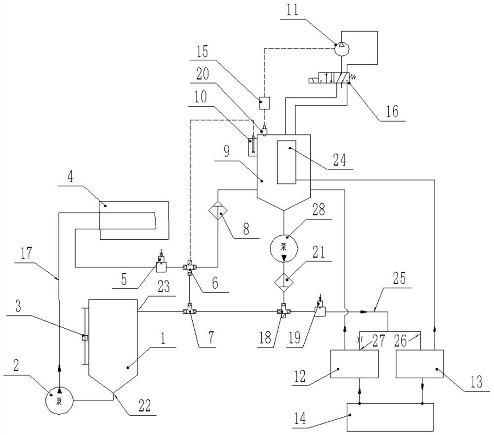
[0029] Such as figure 1As shown, an ink path system of a ceramic inkjet printer includes an ink supply system, a circulation system, an air path system and a control system (not shown in the figure), and the control system is used to control the ink supply system and the circulation system And the air circuit system, the ink supply system includes the ink barrel 1, the ink supply pump 2, the ink supply ink pipe 17, the ink pipes in the ink supply system are collectively referred to as the ink supply ink pipe, and the ink supply pump 2 is used for The liquid in the ink barrel 1 is delivered to the ink supply tube 17, the ink supply tube 17 includes an outlet 22 and a return port 23, and the outlet 22 and the return port 23 are both communicated with the ink barrel 1, The liquid flowing out from the outlet 22 can flow back into the ink barrel 1 thr...


PUM


Abstract

An ink path system for a ceramic inkjet printer, comprising an ink supply system, a re-circulation system, an air way system and a control system; the ink supply system comprises an ink tank (1), an ink supply pump (2), and an ink supply tube (17); the re-circulation system comprises a buffer tank (9), a re-circulation pump (28), an ink inlet cartridge (13), an ink outlet cartridge (12), a re-circulation ink tube and a nozzle (14); the ink tank (1) is in communication with the buffer tank (9), an inner ink tube (24) being provided within the buffer tank (9); the ink inlet cartridge (13) is in communication with a bottom portion of the inner ink tube (24), and the ink outlet cartridge (12) is in communication with a bottom portion of the buffer tank (9).

Description

technical field [0001] The invention relates to ceramic ink-jet printing technology, in particular to an ink path system of a ceramic ink-jet printer. Background technique [0002] Now the ink system of inkjet printers has been developed for a period of time, it is relatively mature, and the competition in the industry is fierce. The existing inkjet printer ink path system has the following disadvantages: [0003] 1. The existing ink system is independently controlled according to the needs of the nozzle, one ink box for entering and one for exiting the ink box, so it needs 2 sets of ink supply systems, 2 sets of air system and 2 sets of control systems to control the entry and exit of two ink cartridges, so The required parts and materials are very large, and the final cost is high, resulting in low market competitiveness; [0004] 2. Now the ink system needs to have stirring motors, heating rods, heating strips and other materials, which will increase the risk of the who...

Claims


Application Information

Patent Timeline
Patent Type & Authority Patents(China)
IPC IPC(8): B41J2/17B41J2/175B41J2/18B41J2/135B41J2/14B41J2/165
CPCB41J2/135B41J2/14B41J2/165B41J2/17B41J2/175B41J2/17596B41J2/18B41J2002/16502
Inventor 温干前林森
Owner KEDA INDUSTRIAL GROUP CO LTD
Learn More