Printing device for plates

A printing and plate technology, applied in the field of plate printing devices, can solve problems such as low printing efficiency, and achieve the effect of improving efficiency and reducing manual operation steps.

Inactive Publication Date: 2020-07-03
卢菲
View PDF5 Cites 20 Cited by
  • Summary
  • Abstract
  • Description
  • Claims
  • Application Information

AI Technical Summary

Problems solved by technology

[0004] In order to overcome the disadvantages of low printing efficiency due to the need to dip the inkpad multiple times and rotate the plate for manual printing, the technical problem of the present invention is to provide a method that can replace manual work and automatically print the plate. Efficient plate printing device

Method used


Image

  • Printing device for plates
  • Printing device for plates
  • Printing device for plates

Examples


Embodiment 1

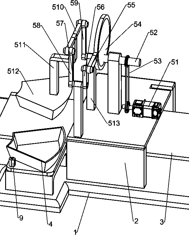
[0046] A plate printing device, such as Figure 1-2 As shown, it includes a base 1, an installation platform 2, a workbench 3, an ink pad plate 4, and a printing mechanism 5. The left side of the base 1 is provided with an installation platform 2, and a workbench 3 is installed between the left and right sides of the base 1. The workbench 3 Located below the installation platform 2, an ink pad plate 4 is provided on the rear side of the right part of the base 1, and a printing mechanism 5 is provided on the rear side of the top of the installation platform 2.

[0047] When it is necessary to print the surface of the plate, the ink pad is first poured into the ink pad plate 4, and the plate is placed on the workbench 3 so that it is located under the printing part of the printing mechanism 5, and then the parts in the printing mechanism 5 are started, and the ink pad is placed on the printing mechanism. Under the action of other components in the printing mechanism 5, the print...

Embodiment 2

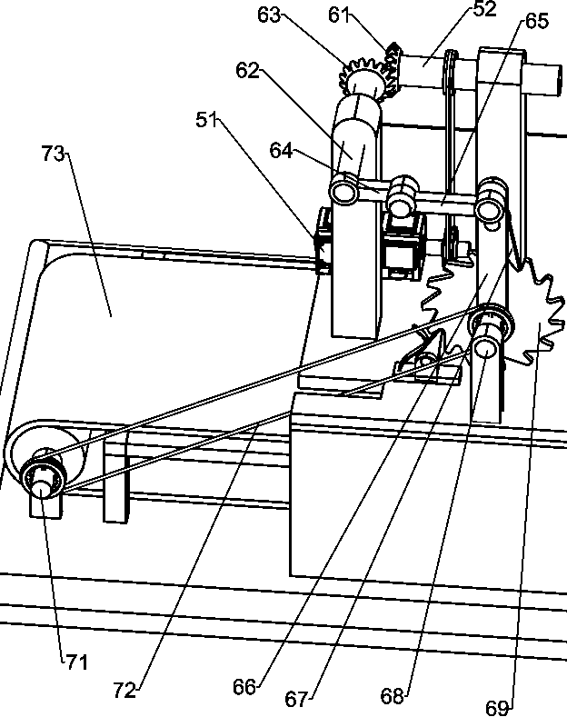
[0049] special reference Figure 1-3 and Figure 5The printing mechanism 5 includes a motor 51, a rotating rod 52, a first belt assembly 53, a rotating disk 54, an annular push rod 55, a first swinging rod 56, a first rotating shaft 57, a second swinging rod 58, a third swinging rod 59, a horizontal Rod 510, connecting rod 511, sponge seal 512 and the first fixed rod 513, motor 51 is installed in the middle of mounting table 2 top left sides, and mounting table 2 top central rotation type is provided with rotating rod 52, rotating rod 52 left sides and motor 51 The first belt assembly 53 is installed between the output shafts, the right end of the rotating rod 52 is connected to the turntable 54, the outer wall of the turntable 54 is covered with an annular push rod 55, and the end of the annular push rod 55 is rotatably connected to the first swing rod 56, and the right side of the mounting table 2 The rear rotating type is provided with a first rotating shaft 57, the end of...

Embodiment 3

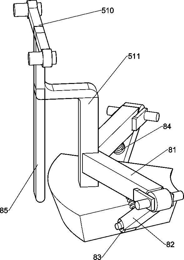
[0054] Overall, such as Figure 1-2 and Figure 4 As shown, it also includes a fixing mechanism 8, the fixing mechanism 8 includes a V-shaped rod 81, a second fixed rod 82, a roller 83, a spring 84 and a third fixed rod 85, and a V-shaped connection rod is arranged between the front and rear sides of the bottom of the connecting rod 511. Rod 81, the front and rear ends of V-shaped rod 81 are all rotatably equipped with second fixed rod 82, the second fixed rod 82 ends on both sides are all equipped with rollers 83, the second fixed rod 82 tops on both sides are connected with V-shaped rod 81 Springs 84 are connected between the bottoms, and a third fixed rod 85 is installed on the left bottom of the connecting rod 511 .


PUM


Abstract

The invention relates to a printing device, in particular to a printing device for plates. The technical problem is providing the printing device for plates, which is characterized in that the devicecan automatically carrying out printing on the plates by replacing manual work, one plate is dipped in red ink paste only once, and the printing efficiency is improved. According to the technical scheme, the printing device for the plates comprises a base, a red ink paste tray and a printing mechanism; a mounting table is arranged on the side portion of the base, a workbench is arranged between the two sides of the base, the workbench is arranged in the horizontal direction, and the workbench is located below the mounting table; the red ink paste tray is arranged at the side portion of the side, close to the mounting table, of the base; and the printing mechanism is arranged at the top of the side, close to he red ink paste tray, of the mounting table. According to the device, through theprinting mechanism, automatic printing on the plates is achieved; meanwhile, the shape of a sponge seal is consistent with the shapes of the plates so that the sponge seal can be in contact with the whole surface of each plate at a time; and through a bolt, the position of the red ink paste tray can be fixed, so that the situation that the sponge seal drives the red ink paste tray to move in the moving process is avoided.

Description

technical field [0001] The invention relates to a printing device, in particular to a plate printing device. Background technique [0002] Now, when plates without patterns are produced, in order to make the plates more beautiful, different patterns are often printed on the surface of the plates manually. When printing, the workers take the stamp sponge to dip the ink pad and print the patterns on the surface of the plate. Then turn the plate manually to print patterns on other parts of the plate. Manually turn the plate intermittently to print patterns on different parts of the plate. However, this plate printing method needs to manually turn the plate multiple times to dip the ink pad, and the printing efficiency is low. . [0003] In order to solve the above-mentioned shortcomings of low printing efficiency during manual printing and the need to turn the plate multiple times to dip the ink pad, a plate printing device that can replace manual work and automatically print ...

Claims


Application Information

Patent Timeline
Patent Type & Authority Applications(China)
IPC IPC(8): B41K3/04B41K3/48B41K3/56B41K3/62B41K3/64
CPCB41K3/04B41K3/48B41K3/56B41K3/62B41K3/64
Inventor 卢菲
Owner 卢菲
Why Eureka
Try Eureka