
Air outlet of automobile air conditioner

An automotive air conditioner and air outlet technology, which is applied in vehicle components, air handling equipment, heating/cooling equipment, etc., can solve the problems of blade damage at the air outlet, affecting the air outlet's air flow regulation effect, etc., and achieve the effect of improving safety.

Active Publication Date: 2020-07-03
英华利汽车零部件(赣州)有限公司
View PDF11 Cites 0 Cited by
  • Summary
  • Abstract
  • Description
  • Claims
  • Application Information

AI Technical Summary

Problems solved by technology

[0004] In the prior art, commonly used automobile air outlets are often used to install some such as perfume, brackets and waste paper tubes, etc., but the conventional structural installation will cause great damage to the blades of the air outlet, which in turn affects the original air outlet. Adjustment effect of airflow

Method used


Image

  • Air outlet of automobile air conditioner
  • Air outlet of automobile air conditioner
  • Air outlet of automobile air conditioner

Examples


Embodiment 1

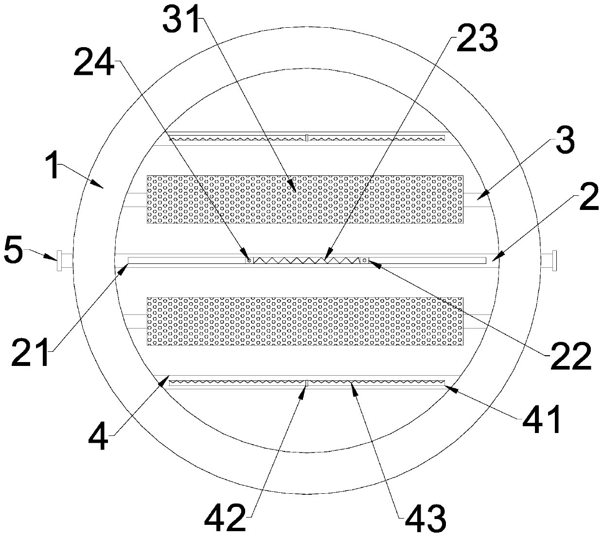
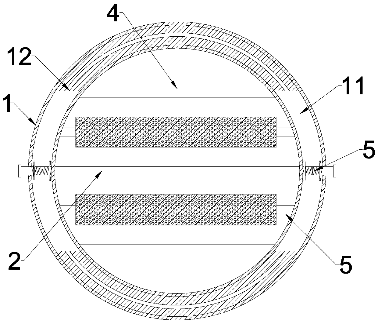
[0022] see Figure 1~2 , in an embodiment of the present invention, an air outlet of an automobile air conditioner includes a ring 1, and the side of the ring 1 is provided with a clamping structure, and the clamping structure includes a clamp for elastic clamping arranged in the annular groove 11 on the side of the ring 1 Pad 12 and stopper 5 for movable clamping, ring 1 are connected with main shaft 2 for fixing, side shaft 4 for support and auxiliary shaft 3 for improving air quality.

[0023] The ring 1 is a ring structure, one side of the ring 1 is embedded with an annular groove 11, and the pad 12 is attached to the inner side walls of the ring groove 11, and is arranged symmetrically with respect to the center of the ring 1. The pad 12 can be made of a soft Made of high-quality rubber or silicone, by aligning one side of the annular groove 11 with the air outlet on the air outlet position of the car, the clip pad 12 can clamp the edge of the original air outlet, thereby...

Embodiment 2

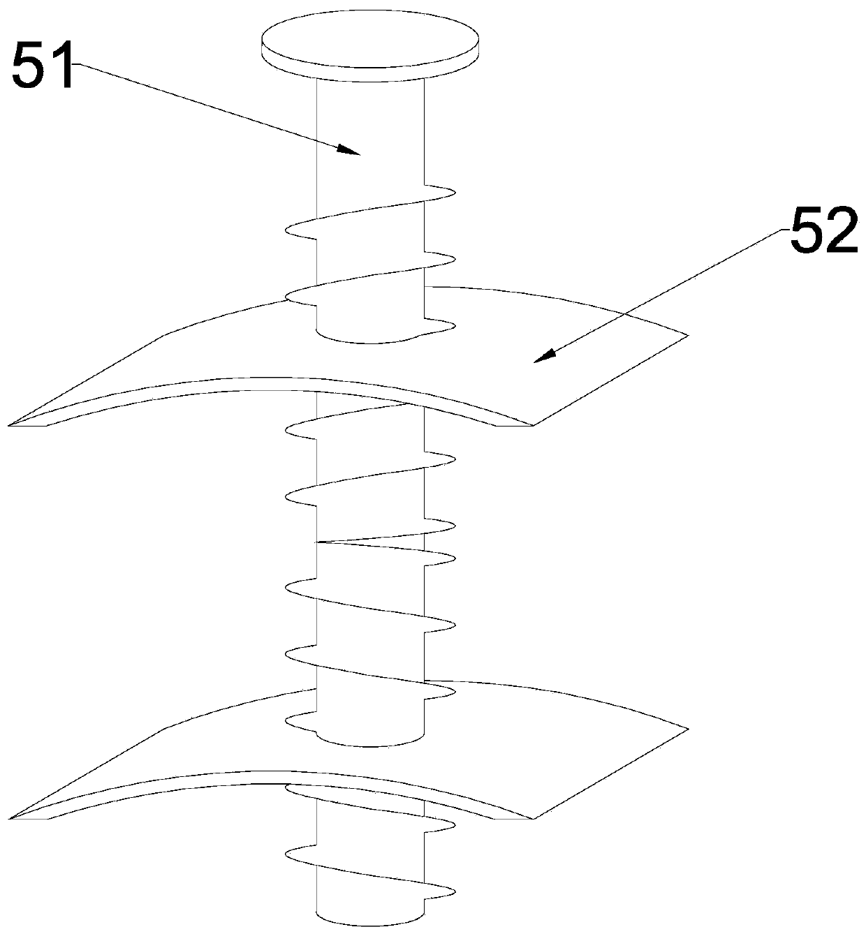
[0028] see image 3 , in the embodiment of the present invention, an air outlet of an automobile air conditioner, on the basis of Embodiment 1, the stoppers 5 are arranged on both sides of the ring 1, and the stoppers 5 on both sides are located between the pads 12, and the stoppers Part 5 includes a screw rod 51 rotatably connected to the side wall of the ring 1 and two sets of cards 52 movably connected to the periphery of the screw rod 51. The screw rod 51 moves through the side wall of the ring ring 1 and extends into the pad 12. The surface of the screw rod 51 There are threads in opposite directions on the periphery. The card 52 is an arc-shaped sheet structure, and the two sets of cards 52 are respectively matched with the opposite threads on the periphery of the screw 51. By rotating the screw 51, the two sets of cards 52 can be driven to form relative motion or reverse motion. Therefore, the edge of the original air outlet at the air outlet position is clamped by the ...


PUM


Abstract

The invention discloses an air outlet of an automobile air conditioner. The air outlet comprises a ring, a clamping structure is arranged on the side face of the ring, the clamping structure comprisesa clamping pad arranged in an annular groove in the side face of the ring and used for elastic clamping and a limiting piece used for movable clamping, and a main shaft used for fixing, a side shaftused for supporting and an auxiliary shaft used for improving the air outlet quality are connected and arranged in the ring. Through cooperation of the clamping pad used for elastic clamping and the limiting piece used for movable clamping, the air outlet structure can be movably assembled at the position of an original air outlet of an automobile, flexible installation is facilitated, and the airoutlet can be suitable for air outlets of various types and sizes; and the main shaft and the side shaft in the ring can be matched to store and fix equipment of various different types and sizes such as a mobile phone or a tablet personal computer, so the safety during driving is conveniently improved, and the original air outlet of the automobile is not damaged.

Description

technical field [0001] The invention relates to the technical field of automobile accessories, in particular to an air outlet of an automobile air conditioner. Background technique [0002] Cars have gradually become a must for many families in today's life. Cars can expand the range of activities of the crowd, improve the convenience of travel, and make it easier to work and live. With the gradual improvement of the level of technology and economy, the quality and comfort of the car are gradually improving, and its various system components and accessories are more suitable for today's daily life. [0003] The air outlet of the car is generally the output end of the car air-conditioning system, which can provide better ride comfort in summer and winter and improve the interior environment of the car through ventilation in other seasons. Automobile air outlets generally have the function of adjusting the air volume and air outlet angle. [0004] In the prior art, commonly ...

Claims


Application Information

Patent Timeline
Patent Type & Authority Applications(China)
IPC IPC(8): B60R11/02B60H1/34B60H3/00B60H3/06
CPCB60H1/34B60H3/0028B60H3/06B60H2003/0691B60R11/0229B60R11/0241B60R2011/0008B60R2011/0059B60R2011/0071
Inventor 贾建亚
Owner 英华利汽车零部件(赣州)有限公司
Learn More