
Ball cage type constant velocity universal joint

A technology of constant velocity universal joints and ball cages, which is applied in the field of universal joints, and can solve the problems of difficult processing of ball cage constant velocity universal joints, increased noise and impact of constant velocity universal joints, and high manufacturing precision requirements. problems, to achieve the effect of reducing frictional resistance, improving carrying capacity and improving efficiency

Inactive Publication Date: 2020-07-03
中科重工设备制造(江苏)有限公司
View PDF4 Cites 1 Cited by
  • Summary
  • Abstract
  • Description
  • Claims
  • Application Information

AI Technical Summary

Problems solved by technology

[0002] Because the ball cage type constant velocity universal joint is difficult to process and requires high precision in manufacturing, the clearance of the ball cage type constant velocity universal joint in the direction of rotation will cause greater vibration and noise during the working process of the ball cage type constant velocity universal joint. When the gap between the universal joints in the direction of rotation is too large, interference will occur between the joints, which will further increase the noise and impact that the constant velocity joint will produce

Method used


Image

  • Ball cage type constant velocity universal joint
  • Ball cage type constant velocity universal joint

Examples


Embodiment Construction

[0020] The present invention is described in further detail now in conjunction with accompanying drawing. These drawings are all simplified schematic diagrams, which only illustrate the basic structure of the present invention in a schematic manner, so they only show the configurations related to the present invention.

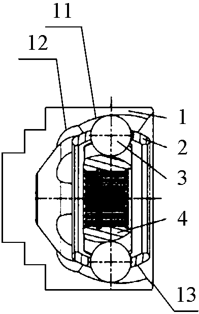
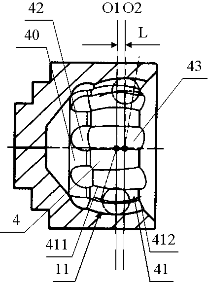
[0021] like Figure 1-2 As shown, the cage type constant velocity universal joint includes a bell shell 1, a cage 2, steel balls 3 and a star sleeve 4; the bell shell 1 is located outside the cage 2, and the star sleeve 4 is located on the cage 2 Inside, the steel balls 3 pass through the notches of the cage 2 and are evenly distributed along the circumference of the cage 2, and the steel balls 3 are in contact with the corresponding grooves of the bell-shaped shell 1 and the star-shaped sleeve 4; the bell-shaped shell 1 The inner channel 11 is an arc channel, and the outer channel 41 of the star sleeve 4 is a double-center arc channel, thereby providing a ca...


PUM


Abstract

The invention relates to a ball cage type constant velocity universal joint which comprises a bell-shaped shell, a retainer, steel balls and a star-shaped sleeve. The ball cage type constant velocityuniversal joint is characterized in that an arc channel is selected as an inner channel of the bell-shaped shell; a double-center arc channel is selected as outer channels of the star-shaped sleeve, and the intersection points of a left arc line and a right arc line of the double-center arc channel meet on a line O1; the positions of the circle centers of the steel balls in the two adjacent outerchannels of the star-shaped sleeve are different, the positions of the circle centers of some of the steel balls meet on the line O1, while the positions of the circle centers of some of the steel balls meet on a line O2; and the linear distance between the line O1 and the line O2 is L. Due to the fact that the inner channel of the bell-shaped shell is the arc channel, the outer channels of the star-shaped sleeve are the double-center arc channel, and the steel balls of the ball cage type constant velocity universal joint are in a three-point contact channel section form, the internal contactcondition of the constant velocity universal joint is improved, the internal contact stress is effectively reduced, accordingly, the bearing capacity of the ball cage type constant velocity universaljoint can be improved, and the service life of the ball cage type constant velocity universal joint is prolonged.

Description

technical field [0001] The invention relates to the technical field of universal joints, in particular to a cage-type constant velocity universal joint. Background technique [0002] Because the ball cage type constant velocity universal joint is difficult to process and requires high precision in manufacturing, the clearance of the ball cage type constant velocity universal joint in the direction of rotation will cause greater vibration and noise during the working process of the ball cage type constant velocity universal joint. When the clearance of the universal joints in the direction of rotation is too large, an interference phenomenon will occur between the interiors of the universal joints, thereby further increasing the noise and impact that will be generated by the constant velocity universal joints. In addition, the universal joint will also be affected by other external conditions to generate vibration. Contents of the invention [0003] The technical problem t...

Claims


Application Information

Patent Timeline
Patent Type & Authority Applications(China)
IPC IPC(8): F16D3/224
CPCF16D3/223F16D2003/22309
Inventor 石光宗刘雷
Owner 中科重工设备制造(江苏)有限公司
Learn More