
Refrigeration house air cooler defrosting system and method based on photoelectric conversion control

A technology of photoelectric conversion and air cooler, which is applied in the direction of refrigerators, refrigeration components, refrigeration and liquefaction, etc., can solve the problems of uneven defrosting of the tube wall of the heat exchange tube, energy waste, storage temperature rise, etc., to avoid storage temperature rising, avoiding the effect of uneven defrosting

Inactive Publication Date: 2020-07-03
山东七十二度制冷设备有限公司
View PDF6 Cites 0 Cited by
  • Summary
  • Abstract
  • Description
  • Claims
  • Application Information

AI Technical Summary

Problems solved by technology

[0004] At present, the defrosting methods mainly include hot air defrosting, water defrosting, electric heating defrosting and the use of timing defrosting method, temperature-time defrosting method, refrigerant superheat defrosting method, temperature difference defrosting method and other control methods. At present, when defrosting water is used for defrosting, the defrosting water stays on the surface of the finned tubes, but due to gravity, it gradually increases from top to bottom along the height direction of the heat exchanger, and most of them are concentrated in the lower part of the heat exchanger , which causes the defrosting of the tube wall of the heat exchange tube to be uneven, and the entire evaporative refrigeration process needs to be stopped for defrosting during use. If the defrosting time is too long, the storage temperature will rise and energy will be wasted.

Method used


Image

  • Refrigeration house air cooler defrosting system and method based on photoelectric conversion control
  • Refrigeration house air cooler defrosting system and method based on photoelectric conversion control

Examples


Embodiment Construction

[0027] It should be noted that the following detailed description is exemplary and intended to provide further explanation of the present disclosure. Unless defined otherwise, all technical and scientific terms used in this disclosure have the same meaning as commonly understood by one of ordinary skill in the art to which this disclosure belongs.

[0028] In the description of the present disclosure, it should be understood that the orientations or positional relationships indicated by the terms "upper", "lower", "top", "bottom", "inner", "outer" etc. are based on those shown in the accompanying drawings. The orientation or positional relationship is only for the convenience of describing the present disclosure and simplifying the description, and does not indicate or imply that the referred device or element must have a specific orientation, be constructed and operated in a specific orientation, and thus cannot be construed as limiting the present disclosure.

[0029] Such a...


PUM


Abstract

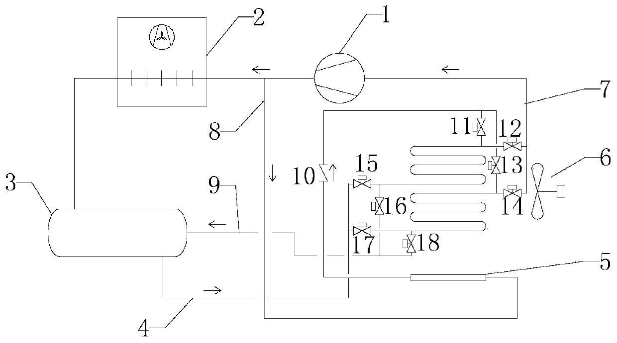
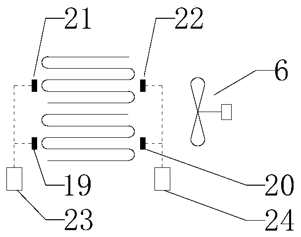
The invention relates to a refrigeration house air cooler defrosting system based on photoelectric conversion control, and belongs to the technical field of freezing equipment. The system comprises anair cooler heat exchanger, a hot air pipe, a liquid returning pipe and a defrosting controller, a heat exchange pipe of a flowing refrigerant is mounted in the air cooler heat exchanger, first electromagnetic valves for controlling a pipeline to be on and off are mounted on an outlet and an inlet of the heat exchange pipe, the outlet of the heat exchange pipe is connected with the hot air pipe used for inputting hot air to the heat exchange pipe, the inlet of the heat exchange pipe is connected with the liquid returning pipe, second electromagnetic valves used for controlling the pipeline tobe on and off are mounted on the hot air pipe and the liquid returning pipe, an emitter used for converting a voltage signal into an optical signal is mounted on the left side in the height directionof the heat exchange pipe, a receiver used for converting the optical signal into the voltage signal is mounted on the right side of the heat exchange pipe in the height direction, the defrosting controller controls the first electromagnetic valves and the second electromagnetic valves to be on and off according to voltage changes to achieve conversion of refrigerating and defrosting work, due tothe defrosting system, uniform defrosting of the pipe wall can be achieved, and meanwhile, energy waste caused by house temperature rise due to too long defrosting time can be avoided.

Description

technical field [0001] The disclosure belongs to the technical field of refrigeration equipment, and in particular relates to a defrosting system and method for a cold storage fan based on photoelectric conversion control. Background technique [0002] The statements herein merely provide background information related to the present disclosure and do not necessarily constitute prior art. [0003] As low-temperature refrigeration equipment, cold storage is widely used in cold chain logistics equipment, and is the key to ensuring the storage quality of food and medicine. In the cold storage, when the surface temperature of the heat exchanger of the air cooler is lower than the dew point temperature, condensation will form on the surface of the heat exchanger, and frost will form when the temperature is lower than the freezing point of water. Over time, a dense layer of frost forms over the entire heat exchanger surface. Due to the low thermal conductivity of the frost layer...

Claims


Application Information

Patent Timeline
Patent Type & Authority Applications(China)
IPC IPC(8): F25B47/02F25B41/04F25B49/02F25B41/20
CPCF25B47/022F25B49/02F25B2347/02F25B41/20
Inventor 李广鹏于乐功肖广玉付建广王新磊
Owner 山东七十二度制冷设备有限公司
Learn More