Vertical single-optical-element rotary Mueller matrix imaging measuring device and method

A Mueller matrix and optical element technology, applied in the field of measurement devices for vertical single optical element rotating Mueller matrix imaging, can solve the problems of low measurement accuracy and complicated operation, and achieve fast measurement process, ensure accuracy, and fast The effect of precise measurement

Pending Publication Date: 2020-07-03
EAST CHINA NORMAL UNIVERSITY
View PDF11 Cites 3 Cited by
  • Summary
  • Abstract
  • Description
  • Claims
  • Application Information

AI Technical Summary

Problems solved by technology

[0004] The object of the present invention is to provide a kind of measuring device and method of vertical single optical element rotating Muller matrix imaging in view of the deficiencies in the prior art. On the basis of the rotating Muller matrix ellipsometer, it solves the complex operation and low measurement accuracy due to the fact that the finally detected transmitted light intensity contains part of the reflected light intensity component, the measurement of the polynomial Fourier coefficient and the transformation solution, etc. problem, the full Mueller matrix elements of the sample can be measured more quickly and efficiently

Method used


Image

  • Vertical single-optical-element rotary Mueller matrix imaging measuring device and method
  • Vertical single-optical-element rotary Mueller matrix imaging measuring device and method
  • Vertical single-optical-element rotary Mueller matrix imaging measuring device and method

Examples


Embodiment Construction

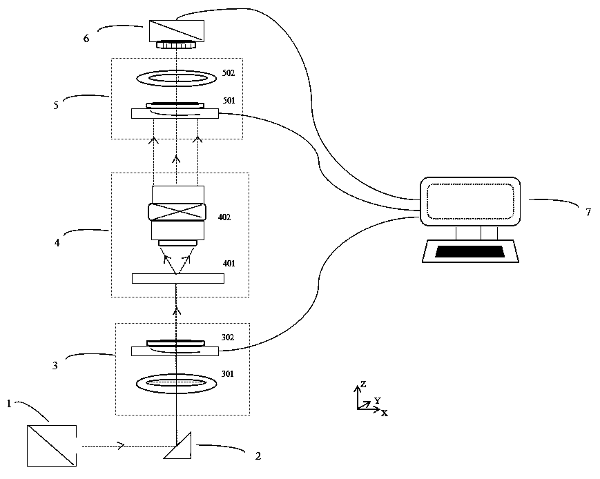
[0029] refer to figure 1 , the present invention will be further described in detail below in conjunction with specific embodiments.

[0030] The rotation of a single optical element in the present invention means that during the working process of a measurement device for Mueller matrix imaging provided by the present invention, the first compensator 302 in the polarization modulation unit 3 is set to have fixed Rotation angle, the second compensator 501 in the polarization demodulation unit 5 is set to rotate at a constant speed at a constant speed.

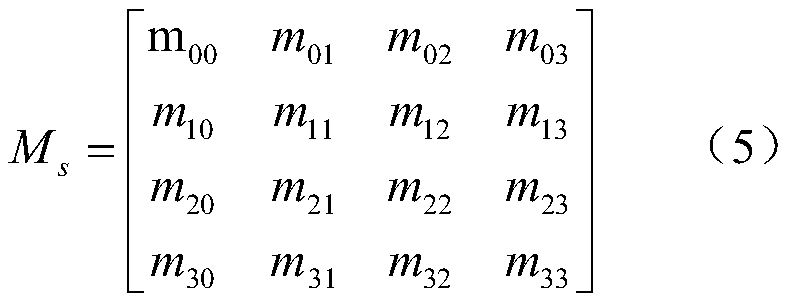
[0031] The non-normalized Muller matrix of the sample to be tested in the present invention is expressed as:

[0032]

[0033] Among them, M s represents the unnormalized Mueller matrix of the sample, m ij (i, j=0, 1, 2, 3) represent 16 elements of the unnormalized Mueller matrix of the sample to be tested.

[0034] The non-normalized Mueller matrix of the sample to be measured can be obtained by summing the Stokes vecto...


PUM


Abstract

The invention discloses a vertical single-optical-element rotary Mueller matrix imaging measuring device and method and belongs to the technical field of polarization optical measurement and micro imaging. The device comprises a light source, a reflector, a polarization modulation unit, a sample measurement unit, a polarization demodulation unit, an optical detector and a calculator which are sequentially arranged along a light path. The device is characterized in that the Stokes-Mueller calculus principle is utilized to establish the relationship between a to-be-measured sample and changing light intensity measured by the optical detector, a Mueller matrix imaging measuring device is adopted to measure a full Mueller matrix of the to-be-measured sample so that all optical anisotropy parameters of the to-be-measured sample are further obtained. The device is advantaged in that problems of complex operation, low measurement precision and the like in the processes of measurement, transformation solution and the like of a polynomial Fourier coefficient are solved, so the measurement speed and precision are improved, and non-destructive, quick and accurate measurement of the structuralmorphology and optical anisotropy parameters of the sample can be realized.

Description

technical field [0001] The invention relates to the technical fields of polarization optical measurement and microscopic imaging, in particular to a measuring device and a measuring method for a vertical single optical element rotating Mueller matrix imaging, that is, the measuring device is used to measure the full Mueller matrix elements and optical components of a sample. A method for measuring anisotropic parameters in a vertical single optical element rotation-type Mueller matrix imaging. Background technique [0002] In recent years, with the rapid development of semiconductor devices, nanomaterials, thin film materials, nanobiomedicine and other technical fields, various functional materials have changed from the original two-dimensional planar structure to a complex three-dimensional structure. As the structure changes, its inherent optical properties will also change. As the most important optical properties of anisotropic materials, optical parameters can directly...

Claims


Application Information

Patent Timeline
IPC IPC(8): G01N21/21
CPCG01N21/21
Inventor 崔晓燕冯晓薇
Owner EAST CHINA NORMAL UNIVERSITY
Why Eureka
Try Eureka