
In-situ detection method and device for hydrogen permeation current of fuel cell stack

A fuel cell stack and in-situ detection technology, which is applied in the direction of fuel cells, circuits, electrical components, etc., can solve the problems that mass spectrometers cannot achieve in-situ detection, the complexity of data sampling and processing is high, and the internal components of the stack are damaged. , to achieve the effects of avoiding complexity, accurate and intuitive measurement results, and rapid measurement process

Pending Publication Date: 2021-12-10
TONGJI UNIV
View PDF3 Cites 0 Cited by
  • Summary
  • Abstract
  • Description
  • Claims
  • Application Information

AI Technical Summary

Problems solved by technology

[0005] The purpose of the present invention is to overcome the problems of high data sampling and processing complexity and the risk of damage to the internal components of the stack in the constant current charging method of the prior art, the in-situ detection cannot be realized by the mass spectrometer detection method, and the test cost is relatively high In order to provide an in-situ detection method and device for the hydrogen permeation current of the fuel cell stack, the hydrogen permeation current of the hydrogen permeation sensing cell under two states is measured to calculate the hydrogen permeation of the proton exchange membrane fuel stack to be tested. Current, realize the advantages of fast and convenient measurement process, wide applicability, accurate and intuitive measurement results, etc.

Method used


Image

  • In-situ detection method and device for hydrogen permeation current of fuel cell stack
  • In-situ detection method and device for hydrogen permeation current of fuel cell stack
  • In-situ detection method and device for hydrogen permeation current of fuel cell stack

Examples


Embodiment 1

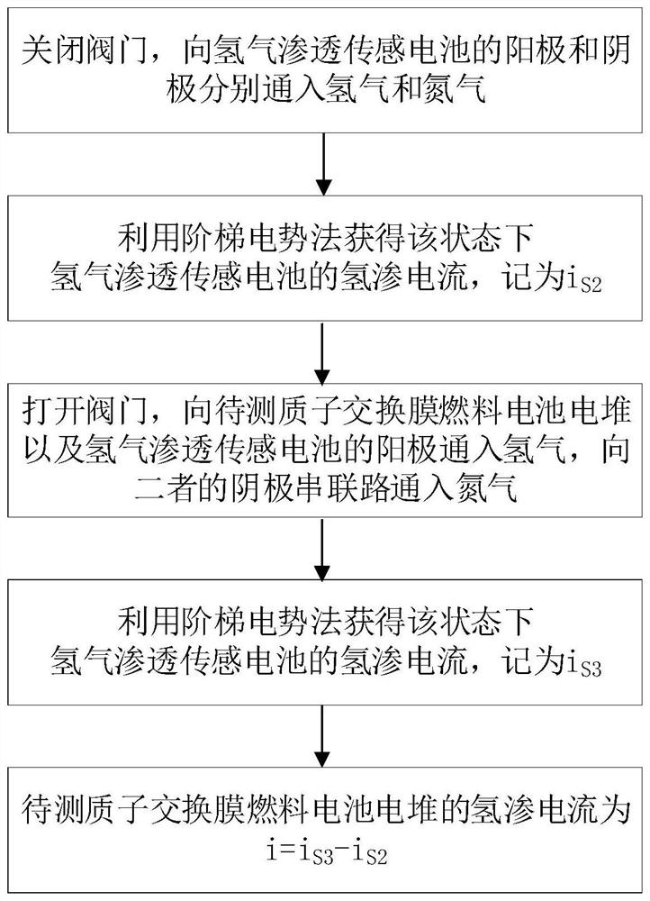
[0043] A fuel cell stack hydrogen permeation current in-situ detection method, such asfigure 1 shown, including the following steps:

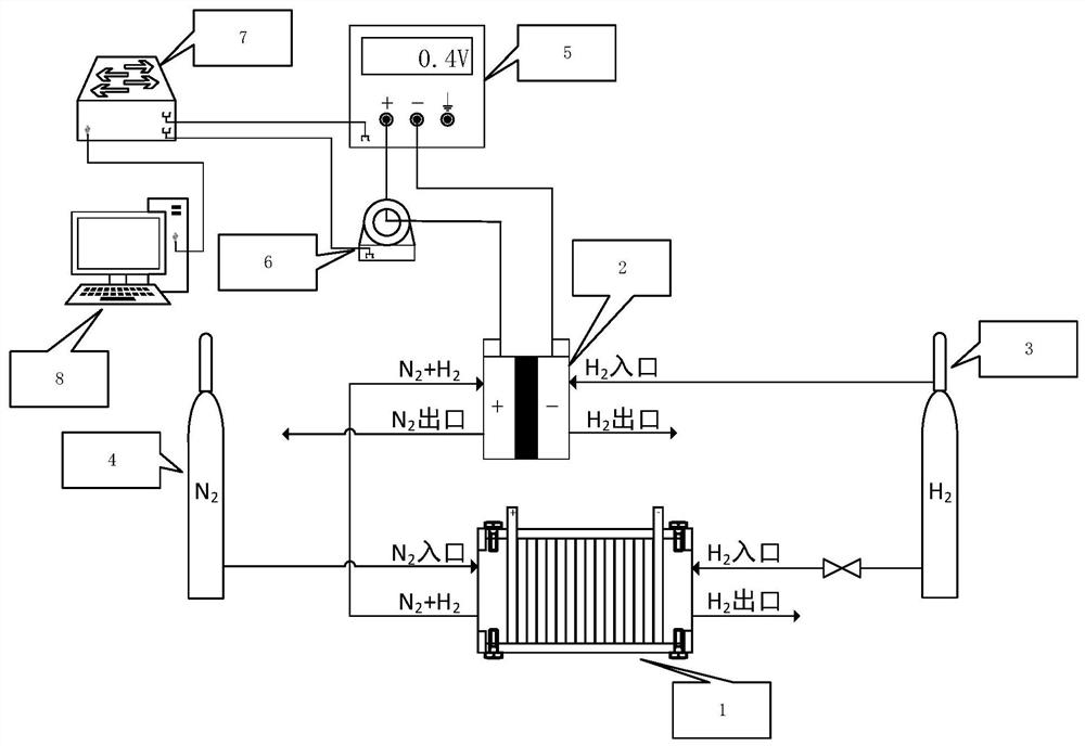
[0044] S1. Obtain the proton exchange membrane fuel cell stack and the hydrogen permeation sensing cell to be tested, and connect the cathode outlet of the proton exchange membrane fuel cell stack to the cathode inlet of the hydrogen permeation sensing cell to form a cathode connection path;

[0045] S2, feed nitrogen gas into the cathode connecting path, feed hydrogen gas into the anode of the hydrogen gas permeation sensor cell, measure the hydrogen permeation current of the hydrogen gas permeation sensor cell in the current state, denoted as i S2 .

[0046] S3. Feed nitrogen gas into the cathode connecting path, feed hydrogen gas into the anode of the proton exchange membrane fuel cell stack to be tested and the anode of the hydrogen permeation sensing cell, measure the hydrogen permeation current of the hydrogen permeation sensing cell in t...


PUM


Abstract

The invention relates to an in-situ detection method and device for hydrogen permeation current of a fuel cell stack. The method comprises the steps of connecting a cathode outlet of a proton exchange membrane fuel cell stack to be detected with a cathode inlet of a hydrogen permeation sensing cell; introducing nitrogen into a cathode connecting circuit, introducing hydrogen into the anode of the hydrogen permeation sensing cell, and measuring the hydrogen permeation current iS2 of the hydrogen permeation sensing cell in the current state; introducing nitrogen into a cathode connecting circuit, introducing hydrogen into the anode of the proton exchange membrane fuel cell stack to be detected and the anode of the hydrogen permeation sensing cell, and measuring the hydrogen permeation current iS3 of the hydrogen permeation sensing cell in the current state; and obtaining a difference value between the hydrogen permeation current iS3 and the hydrogen permeation current iS2, wherein the difference value is a detection result of the hydrogen permeation current of the cell stack to be detected. Compared with the prior art, the method can effectively avoid the complexity of hydrogen permeation current measurement of the cell stack and the risk of potential damage to the cell stack during hydrogen permeation measurement, the measurement process is rapid and convenient, the applicability is wide, and the measurement result is accurate and visual.

Description

technical field [0001] The invention relates to the technical field of hydrogen permeation current measurement of a proton exchange membrane fuel cell stack, in particular to an in-situ detection method and device for hydrogen permeation current of a fuel cell stack. Background technique [0002] The membrane electrode of proton exchange membrane fuel cell (referred to as PEMFC) is composed of gas diffusion layer, catalyst layer and proton exchange membrane. The role of the proton exchange membrane includes isolating hydrogen and oxygen, blocking electrons and passing protons. Protons are transferred from the anode to the cathode through the proton exchange membrane, forming a circuit and generating an electric current. However, due to the concentration gradient of hydrogen on both sides of the proton exchange membrane and its own defects, a small amount of hydrogen permeates from the anode to the cathode through the proton exchange membrane, resulting in the reduction of e...

Claims


Application Information

Patent Timeline
IPC IPC(8): H01M8/04537
CPCH01M8/04597H01M8/04589Y02E60/50
Inventor 梁永浩马天才姚乃元杨彦博
Owner TONGJI UNIV
Learn More