Ecological rock-soil mechanics slope protection test device under simulated rainfall condition
A technology of rock and soil mechanics and test equipment, applied in the field of geotechnical engineering, can solve the problems of affecting the effect of slope plant soil consolidation, failure to realize automatic adjustment of rainfall intensity, and great danger of debris flow
- Summary
- Abstract
- Description
- Claims
- Application Information
AI Technical Summary
Problems solved by technology
Method used
Image
Examples
Embodiment 1
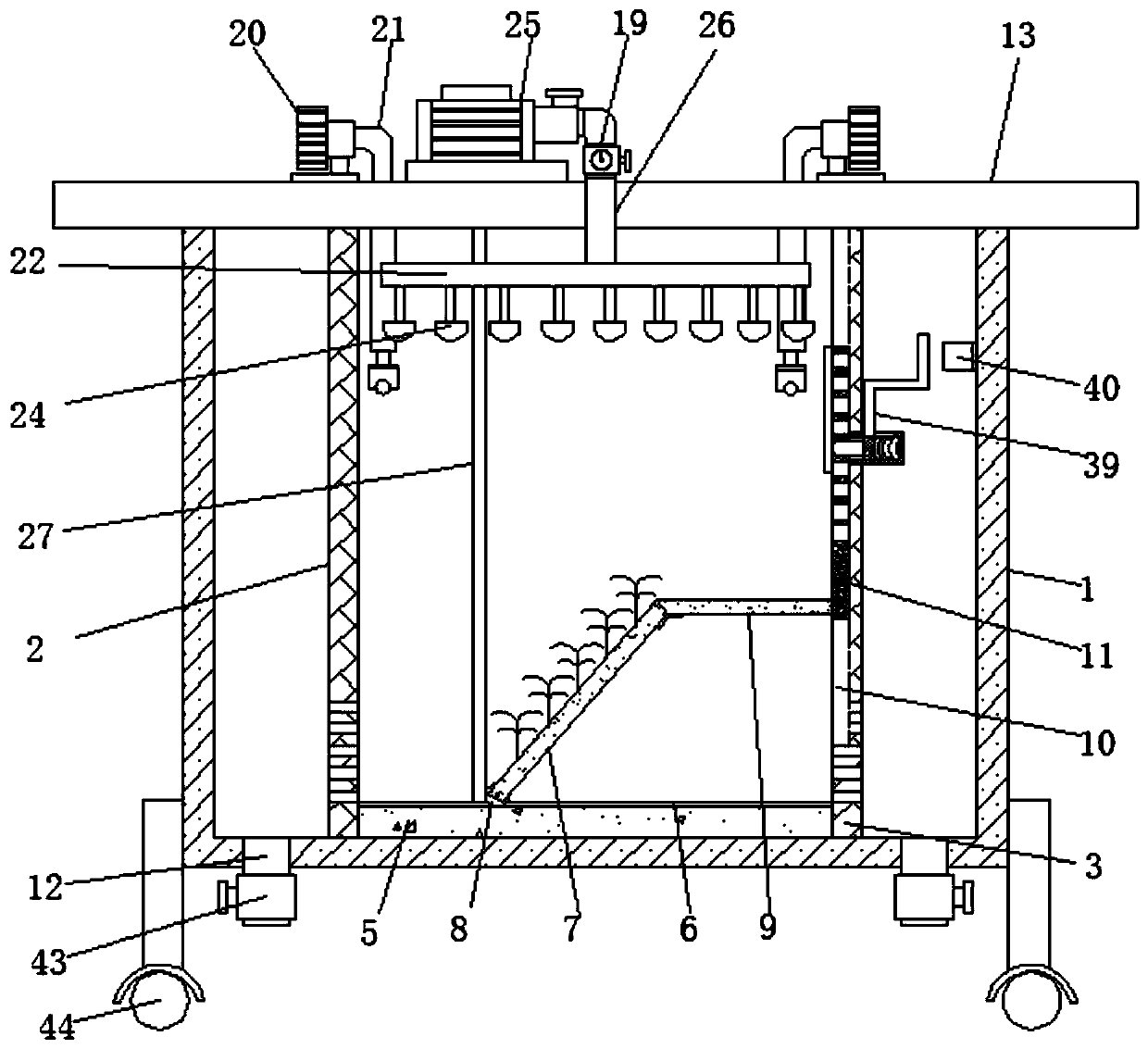
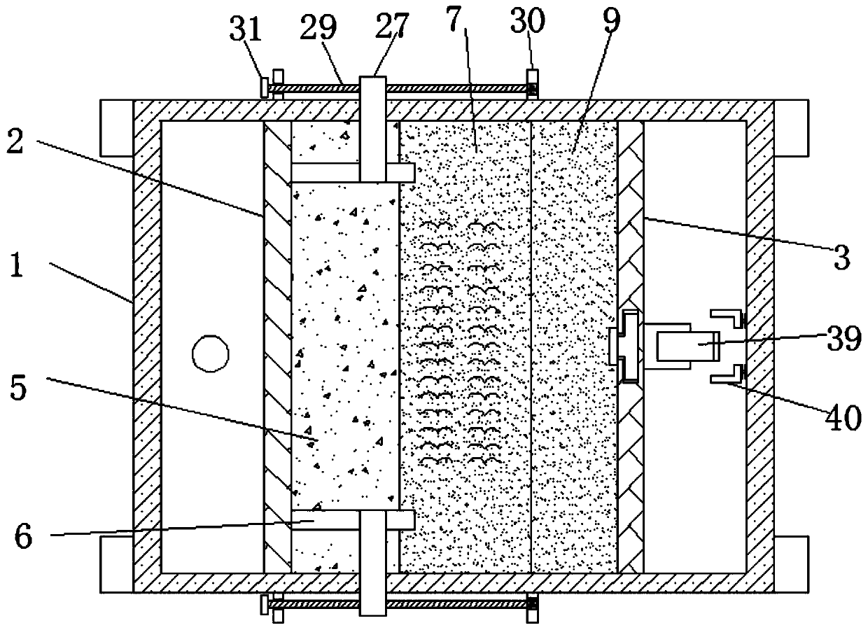
[0040] see Figure 1-10According to an embodiment of the present invention, an ecological rock-soil mechanical slope protection test device under a simulated rainfall condition includes an experimental box 1, the four corners of the bottom of the experimental box 1 are connected with universal wheels 44, and the universal wheels 44 are convenient for testing the experimental box 1. Carry out the operation of moving, and what universal wheel 44 adopts can be fixed universal wheel, and the interior of described experiment box 1 is fixedly connected with dividing plate one 2 and dividing plate two 3, and described dividing plate one 2 and described dividing plate The bottom of two 3 has a plurality of water holes 4, a plurality of water holes 4 facilitate water flow through the partition one 2 and the partition two 3, between the partition one 2 and the partition two 3 The backing plate 5, the backing plate 5 is located at the inner bottom of the test box 1, the height of the bac...
Embodiment 2
[0047] see Figure 1-2 and Figure 5-7 , the limiting mechanism includes a limiting rod 27 and a slider 28, the chute one 6 is provided with a limiting rod 27 near the pulley 8, and the bottom of the limiting rod 27 is fixedly connected with a sliding block 28, so The slide block 28 is located in the chute one 6 and matches with the chute one 6, the slide block 28 can limit the stop bar, and the top of the stop bar 27 is located at the top of the experiment box 1. The outside and is connected with the adjustment mechanism, the adjustment mechanism includes a screw rod 29, a fixed block 30 and a rotating block 31, and the limit rod 27 is screwed with a screw rod 29 at one end of the outside of the experiment box 1, and the limit rod 27 is opened. The screw hole that can be threadedly connected with screw rod 29 is arranged, and the two ends of described screw rod 29 are movably connected with fixed block 30, and screw rod 29 is movably connected with fixed block 30 by bearing,...
Embodiment 3
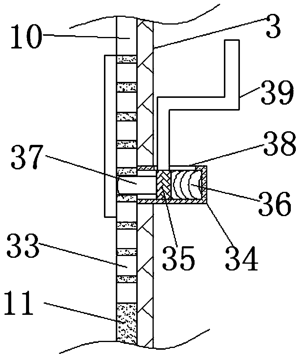
[0050] see Figure 1-3 , the fixed mechanism one includes a through hole 33, a fixed sleeve 34, a movable block 35, a spring 36 and a protrusion 37, and the middle part of the side of the partition plate two 3 away from the experimental board 7 is fixedly connected with a fixed sleeve 34, so The inside of the fixed sleeve 34 is connected to the movable block 35 through a spring 36, and a plurality of through holes 33 are opened on the slide bar 11, and a protrusion 37 is connected to the side of the movable block 35 away from the spring 36, and the The port of the projection 37 runs through the partition plate 2 3 and is located in the through hole 33, the top of the fixed sleeve 34 has a movable hole 38, and the top of the movable block 35 is fixedly connected with a push rod 39, so The top of the push rod 39 passes through the movable hole 38 and is located on the outside of the fixed sleeve 34. The test box 1 is close to the inside of the side of the partition plate 2 3 and...
PUM
 Abstract
Description
Claims
Application Information
 - R&D
- Intellectual Property
- Life Sciences
- Materials
- Tech Scout
- Unparalleled Data Quality
- Higher Quality Content
- 60% Fewer Hallucinations
Browse by: Latest US Patents, China's latest patents, Technical Efficacy Thesaurus, Application Domain, Technology Topic, Popular Technical Reports.
© 2025 PatSnap. All rights reserved.Legal|Privacy policy|Modern Slavery Act Transparency Statement|Sitemap|About US| Contact US: help@patsnap.com


