Optical biological fingerprint identification structure and image edge relative illuminance improving method

A fingerprint identification and biological technology, applied in the direction of optics, optical components, characters and pattern recognition, etc., to achieve the effect of increasing the relative illuminance of the edge, increasing the relative illuminance, and increasing the amount of incoming light

Pending Publication Date: 2020-07-03
SHANGHAI FINGER TECH CO LTD
View PDF0 Cites 0 Cited by
  • Summary
  • Abstract
  • Description
  • Claims
  • Application Information

AI Technical Summary

Problems solved by technology

The optical biometric fingerprint identification structure solves the problem of edge shadows, increases the amount of light passing through the edge area, improves the relative illuminance of the image edge, and improves the accuracy of biometric identification

Method used


Image

  • Optical biological fingerprint identification structure and image edge relative illuminance improving method
  • Optical biological fingerprint identification structure and image edge relative illuminance improving method
  • Optical biological fingerprint identification structure and image edge relative illuminance improving method

Examples


Embodiment 1

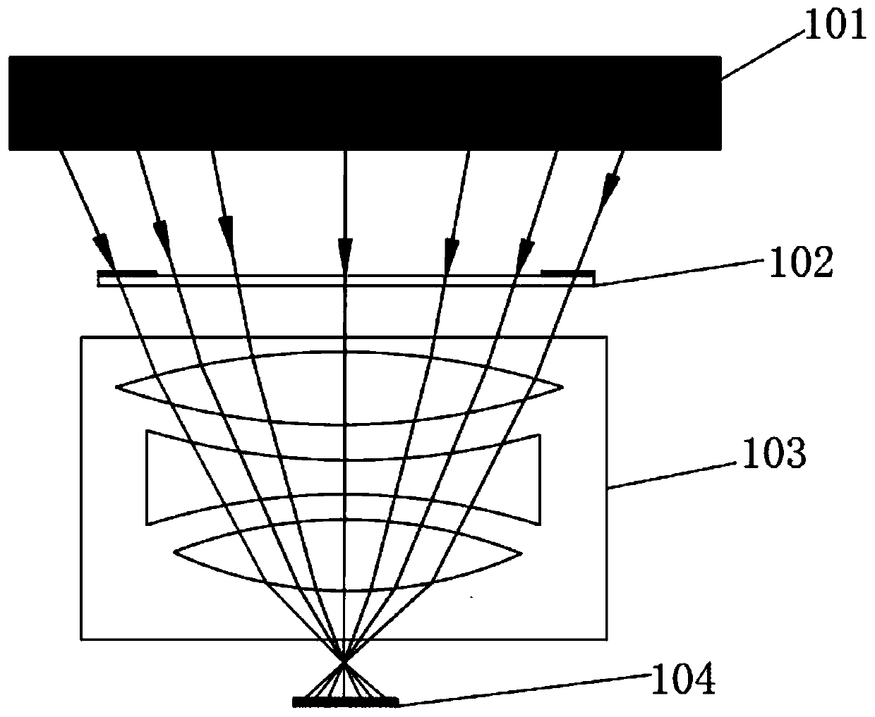
[0039] Please refer to figure 1 , figure 1 A cross-sectional schematic diagram of an optical biometric fingerprint identification structure provided for the invention.

[0040] This embodiment provides an optical biometric fingerprint identification structure, which captures an optical image signal, converts the optical image signal into an electrical signal, and transmits the electrical signal to the outside of the module.

[0041] In this embodiment, the optical biometric fingerprint identification structure includes an optical filter 102, an optical lens 103, a CMOS image sensor, and an image processing and identification algorithm module 104. The optical biometric fingerprint identification structure is located below the OLED display screen 101, and the optical filter 102 Located between the optical lens 103 and the OLED display 101 , the CMOS image sensor and image processing and recognition algorithm module 104 are located below the optical lens 103 .

[0042] The opti...

Embodiment 2

[0053] Compared with Embodiment 1, this embodiment is the same as Embodiment 1 except that the optical filter 102 is different.

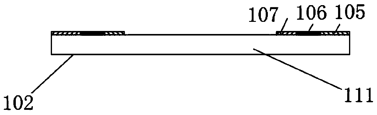
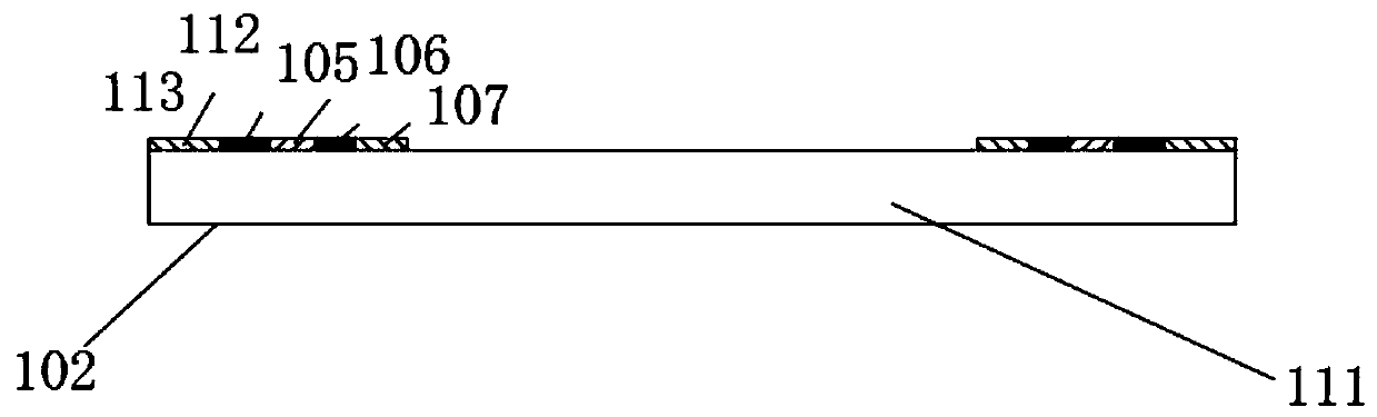
[0054] Please refer to image 3 , image 3 It is another optical filter 102. In this embodiment, the optical filter 102 includes a filter substrate 111, and the edge position of the filter substrate 111 is sequentially provided with a first band 107, a second band 106, Any of the third band 105, the fourth band 112, and the fifth band 113, the first band 107, the second band 106, the third band 105, the fourth band 112, and the fifth band 113 Light transmittance>light transmittance of the filter substrate 111 . When installed, the first band 107, the second band 106, the third band 105, the fourth band 112, and the fifth band 113 correspond to the shadow areas of the image formed by the optical system.

[0055] Further, the light transmittance of the filter substrate 111

Embodiment 3

[0062] Please refer to Figure 5 , Figure 5 A cross-sectional schematic diagram of an optical biometric fingerprint identification structure provided for the invention.

[0063] This embodiment provides an optical biometric fingerprint identification structure, which captures an optical image signal, converts the optical image signal into an electrical signal, and transmits the electrical signal to the outside of the module.

[0064] In this embodiment, the optical biometric fingerprint identification structure includes an optical lens 103, a CMOS image sensor and an image processing and identification algorithm module 104, the optical biometric fingerprint identification structure is located below the OLED display 101, and the optical lens 103 is located between the OLED display 101 and Between the CMOS image sensor and the image processing and recognition algorithm module 104 , the optical lens 103 includes a first lens 108 .

[0065] Please refer to Figure 6 , Figure...


PUM


Abstract

The invention discloses an optical biological fingerprint identification structure. The system comprises an optical lens, and a CMOS image sensor and an image processing and recognition algorithm module which are located below the optical lens. The optical lens comprises a first lens, the first lens comprises a first lens body, the edge position of the optical biological fingerprint identificationstructure is sequentially provided with a first zone, a second zone... An nth zone from inside to outside, and n is a natural number greater than 0. The method has the advantages of increasing the light flux of an edge area, improving the relative illuminance of image edges and improving the biological recognition accuracy.

Description

technical field [0001] The invention belongs to the field of optical image acquisition, and in particular relates to an optical biometric fingerprint identification structure, a display device, electronic equipment and a method for improving the relative illuminance of image edges. Background technique [0002] The development of biometric technology is changing with each passing day, especially in the mobile phone industry. At present, full-screen mobile phones have become mainstream in the mobile phone market, and biometric fingerprint recognition under the screen has also become the main unlocking method for full-screen mobile phones. [0003] In the development of under-screen biometric fingerprint recognition, optical biometrics often use macro cameras placed under the screen to perform optical imaging of fingerprints. Due to the large angle between the light at the edge of the wide-angle lens and the optical axis, light is lost, and the edge of the resulting image The ...

Claims


Application Information

Patent Timeline
Patent Type & Authority Applications(China)
IPC IPC(8): G06K9/00G02B5/28
CPCG02B5/285G06V40/1324
Inventor 张昂黄昊姜洪霖杨成龙张顺星
Owner SHANGHAI FINGER TECH CO LTD
Why Eureka
Try Eureka