
Connecting structure of electric conducting rod and electric connecting device

A technology of electrical connection device and connection structure, applied in the direction of connection where permanent deformation plays a role, can solve the problems of increased production cost, complicated welding process, bolts, and increased standard parts, so as to reduce the use and realize contact and fixed connection , the effect of reducing production costs

Active Publication Date: 2020-07-03
PINGGAO GRP +1
View PDF10 Cites 0 Cited by
  • Summary
  • Abstract
  • Description
  • Claims
  • Application Information

AI Technical Summary

Problems solved by technology

[0004] The purpose of the present invention is to provide a connection structure between a conductive rod and an electrical connection device, which is used to solve the problem that the welding process of the connecting head and the conductive rod in the existing electrical connection device is complicated and the use of bolts increases the use of standard parts. Increased production costs

Method used

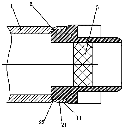
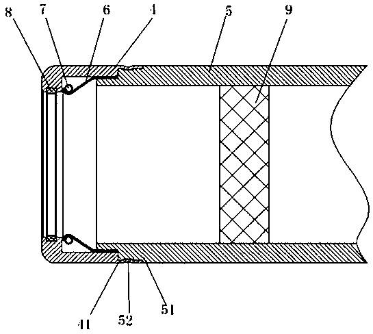
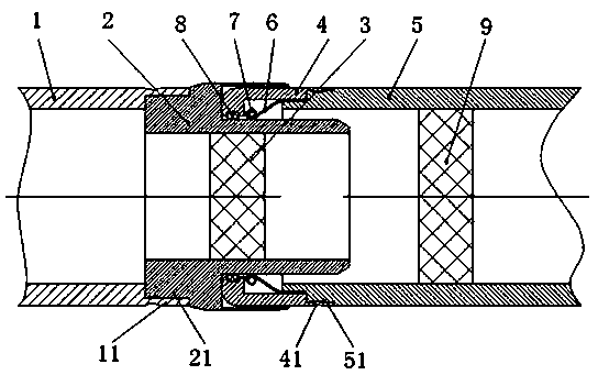

Image

  • Connecting structure of electric conducting rod and electric connecting device
  • Connecting structure of electric conducting rod and electric connecting device
  • Connecting structure of electric conducting rod and electric connecting device

Examples


Embodiment Construction

[0027] In order to make the objectives, technical solutions, and advantages of the present invention clearer, the following further describes the present invention in detail with reference to the accompanying drawings and embodiments. It should be understood that the specific embodiments described here are only used to explain the present invention and not to limit the present invention, that is, the described embodiments are only a part of the embodiments of the present invention, rather than all the embodiments. The components of the embodiments of the present invention generally described and illustrated in the drawings herein may be arranged and designed in various different configurations.

[0028] Therefore, the following detailed description of the embodiments of the present invention provided in the accompanying drawings is not intended to limit the scope of the claimed invention, but merely represents selected embodiments of the present invention. Based on the embodiment...


PUM


Abstract

The invention relates to a connecting structure of an electric conducting rod and an electric connecting device. The connecting structure comprises an electric conducting rod and a connecting head, wherein the connecting head is fixed at the front end of the electric conducting rod, the front end of the electric conducting rod or the rear end of the connecting head is provided with a pressure welding deformation section, the pressure welding deformation section is provided with an insertion cavity, the rear end of the connecting head or the front end of the electric conducting rod is providedwith a corresponding insertion section, the insertion section is used for being inserted into the insertion cavity of the pressure welding deformation section, a pressure welding deformation part is arranged on the side wall of the pressure welding deformation section, the pressure welding deformation part deforms towards the radial inner side of the pressure welding deformation section so as to be fixed on the insertion section in a pressure welding manner, and the connecting head and the electric conducting rod are inserted into the insertion cavity of the pressure welding deformation section through the insertion section. According to the invention, the pressure welding deformation section deforms inwards in the radial direction so as to be fixed to the insertion section in a pressure welding manner, so that the effective contact and fixed connection between the connecting head and the electric conducting rod are achieved, the mode that the connecting head and the conducting rod arewelded and fixed to a bolt for fixed connection is avoided, use of standard member is reduced, and the production cost of the electric connection device is reduced.

Description

Technical field [0001] The invention belongs to the field of electrical connection devices, and particularly relates to a connection structure between a conductive rod and an electrical connection device. Background technique [0002] Electrical connection devices are widely used components in gas-insulated metal-enclosed switch (GIS) and gas-insulated metal-enclosed transmission lines (GIL). The main function is to conduct rated current and instantaneous fault current in the main circuit, and the quality of the electrical connection device The quality directly affects the reliability of the equipment and the safe operation of the power grid. [0003] At present, the contact base, the contact finger base and the conductive rod in the electrical connection device are connected together by welding or bolts. The welding method has the following problems. In order to ensure the electric field needs, the welding seam needs to be polished, which causes welding The efficiency is low, and...

Claims


Application Information

Patent Timeline
Patent Type & Authority Applications(China)
IPC IPC(8): H01R4/20
CPCH01R4/20
Inventor 王红超李凯李艳洁徐仲勋宋继光李新刚司晓闯许东杰尹世献
Owner PINGGAO GRP
Learn More