Vacuum generation device

A technology of vacuum generating device and vacuum pump, which is applied to pump devices, components of pumping devices for elastic fluids, machines/engines, etc. The effect of suppressing enlargement

Inactive Publication Date: 2020-07-03
ULVAC KIKO
View PDF7 Cites 0 Cited by
  • Summary
  • Abstract
  • Description
  • Claims
  • Application Information

AI Technical Summary

Problems solved by technology

On the other hand, when transporting a patient who needs suction treatment, since the negative pressure cannot be obtained from the tube terminal, it is necessary to prepare a separate suction device with a negative pressure source

Method used


Image

  • Vacuum generation device
  • Vacuum generation device
  • Vacuum generation device

Examples


Embodiment Construction

[0039] Hereinafter, embodiments of the present invention will be described with reference to the drawings.

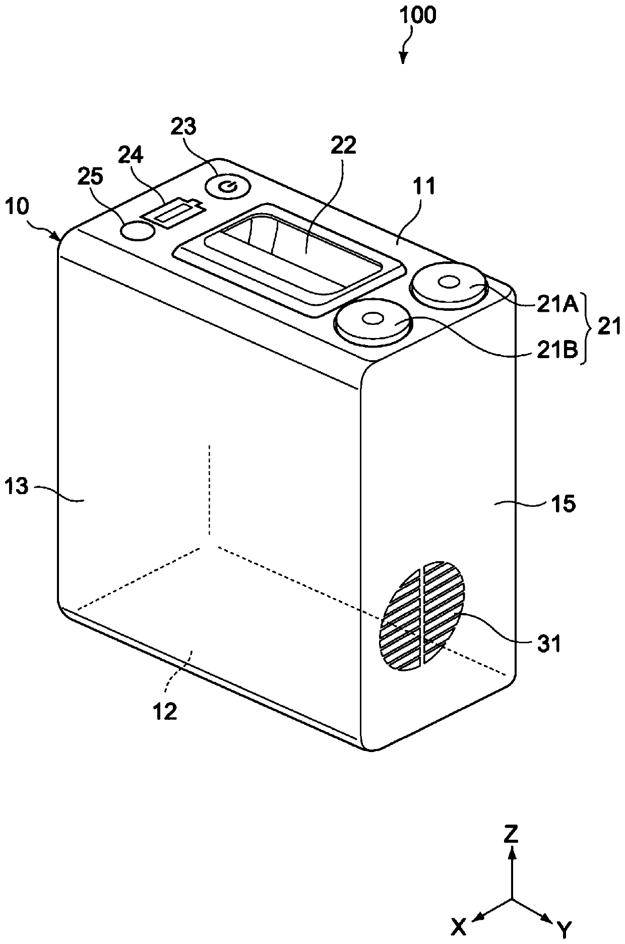
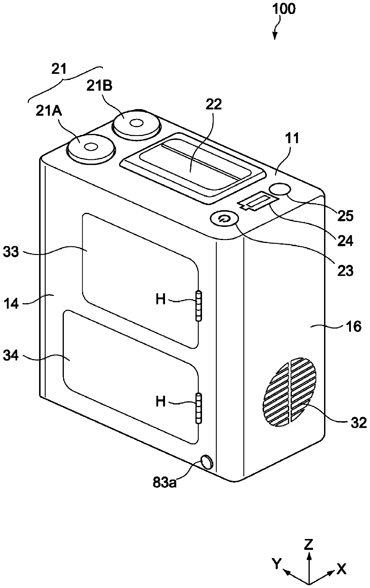
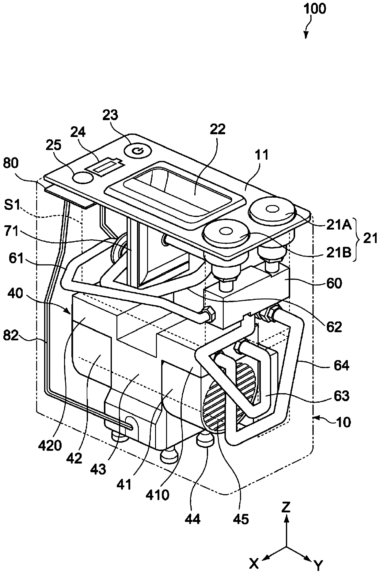
[0040] figure 1 It is a perspective front view showing the whole of the vacuum generator 100 according to one embodiment of the present invention, figure 2 is its stereoscopic rear view. image 3 is a perspective front view showing the internal structure of the vacuum generator 100, Figure 4 is its stereoscopic rear view. Figure 5 It is a block diagram showing the configuration of the vacuum generator 100 .

[0041] exist Figure 1 ~ Figure 4 Among them, the X-axis, Y-axis, and Z-axis represent three axial directions orthogonal to each other, the X-axis direction corresponds to the front-back direction (depth direction), the Y-axis direction corresponds to the left-right direction (width direction), and the Z-axis direction corresponds to Up and down direction (height direction).

[0042] The vacuum generator 100 of the present embodiment has a housing 10 and a...


PUM


Abstract

A vacuum generation device according to one aspect of the present invention is provided with a case, a vacuum pump, and a storage battery. The housing has: a top surface section having a handle part and a pipping terminal connectable to a suction mechanism; and a bottom surface section. The vacuum pump has first and second pump chambers that are accommodated in the housing and connected to the piping terminal in parallel, and is installed on the bottom surface section. The storage battery is accommodated in the housing and supplies power to the vacuum pump.

Description

technical field [0001] The present invention relates to a portable vacuum generating device that can be used, for example, as a negative pressure source of a medical suction device. Background technique [0002] In medical facilities with large-scale fixed suction supply equipment, a pipe terminator (output port) connected to the suction supply equipment is installed on the wall of the ward or treatment room, and the suction equipment is connected to the pipe terminal to obtain Attract the required negative pressure. On the other hand, when transporting a patient who needs suction treatment, since negative pressure cannot be obtained from the tube terminal, it is necessary to prepare a separate suction device with a negative pressure source. [0003] For example, Patent Document 1 discloses an endoscope device having a suction container and a suction tube connected to a suction device, and Patent Document 2 discloses a portable suction pump unit having an internally dispose...

Claims


Application Information

Patent Timeline
Patent Type & Authority Applications(China)
IPC IPC(8): F04B41/00A61M1/00F04B37/16F04B39/16
CPCA61M1/00F04B37/16F04B39/16F04B41/00F04B53/16F04B53/20
Inventor 桥本泰弘宫田一秋西釜壮一郎米永秀一林浩
Owner ULVAC KIKO
Why Eureka
Try Eureka