Method for manufacturing optical device

A technology for an optical device and a manufacturing method, which is applied to optics, optical elements, optical elements, etc., can solve the problems of difficulty in precision cutting and easy contamination of reflective parts, and achieve the effect of reducing manufacturing costs.

Active Publication Date: 2020-07-03
LETINAR CO LTD
View PDF10 Cites 0 Cited by
  • Summary
  • Abstract
  • Description
  • Claims
  • Application Information

AI Technical Summary

Problems solved by technology

However, such a method has unexpected curvature or wear problems that may make precise cutting difficult and the reflective part is easily contaminated.

Method used


Image

  • Method for manufacturing optical device
  • Method for manufacturing optical device
  • Method for manufacturing optical device

Examples


Embodiment Construction

[0044] Hereinafter, preferred embodiments of the present invention will be described in detail with reference to the accompanying drawings, so that those skilled in the art of the present invention can easily implement the present invention.

[0045] First, an augmented reality realization device 100 to which the optical device 10 of the present invention is applied will be described. Such an augmented reality realization device 100 is based on the contents described in Korean Patent Registration No. 10-1660519 filed by the applicant.

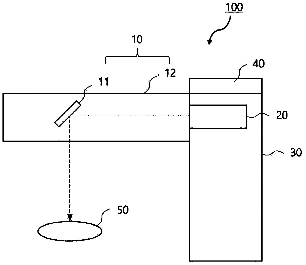
[0046] figure 1 It is a diagram schematically showing the configuration of an augmented reality realization device 100 to which the optical device 10 of the present invention is applied.

[0047] refer to figure 1 The augmented reality realization device 100 includes an optical device 10 composed of a reflection part 11 and an optical element 12 , an image output part 20 that outputs image light corresponding to an augmented reality image, an...


PUM


Abstract

The present invention relates to a method for manufacturing an optical device, the method comprising the steps of: providing first and second optical elements having a pair of opposite surfaces; forming a reflective part on the surface of the first optical element among the pair of opposite surfaces; and bringing the first and second optical elements into close contact with each other and fixing the same to each other to form an optical device.

Description

technical field [0001] The present invention relates to a method of manufacturing an optical device, and more specifically, to a method capable of efficiently manufacturing an optical device in which a small reflection portion is arranged inside an optical element. Background technique [0002] The so-called augmented reality (Augmented Reality) is a technology that superimposes a virtual screen (virtual world) on the real world seen by the user's naked eyes. Since a single image is presented by combining the virtual world with additional information in real time in the real world, the initial stage Also known as Mixed Reality. [0003] Such augmented reality has been studied starting from the development of a see-through HMD (Head Mounted Display), but it has a different meaning from virtual reality (Virtual Reality). Since virtual reality immerses users in a virtual environment, users cannot see the actual environment. On the contrary, in augmented reality, users can see ...

Claims


Application Information

Patent Timeline
Patent Type & Authority Applications(China)
IPC IPC(8): G02B27/01G02B5/04G02B17/08
CPCG02B27/0172G02B27/62B29D11/0073B29D11/00769G02B5/04G02B17/08G02B2027/0194G02B1/04
Inventor 河政勋
Owner LETINAR CO LTD
Why Eureka
Try Eureka