
Fishing wire wheel with brake system on both sides of spool

A braking system and fishing reel technology, applied in fishing reels, fishing, applications, etc., can solve the problems of inconvenient operation, unbalanced reel cup brakes, and large space occupied by the magnetic brake system.

Pending Publication Date: 2020-07-07
威海吉泰精工金属制造有限公司
View PDF0 Cites 0 Cited by
  • Summary
  • Abstract
  • Description
  • Claims
  • Application Information

AI Technical Summary

Problems solved by technology

[0004] Aiming at the shortcomings and deficiencies in the prior art, the present invention proposes a method that can solve the problem of unbalanced spool brakes, and the magnetic brake system takes up a lot of space, is inconvenient to operate, and cannot really close the electromagnetic force generated by the magnet on the rotating spool The braking system is located on both sides of the spool of the fishing reel

Method used


Image

  • Fishing wire wheel with brake system on both sides of spool

Examples


Embodiment 1

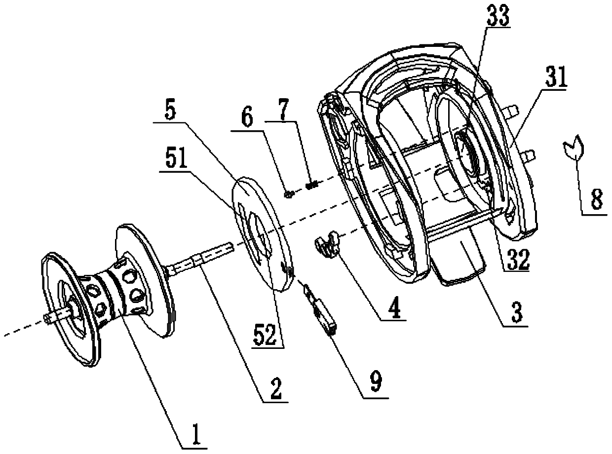
[0028] Embodiment 1, the brake system I on the left (right) side of the wire cup 1 is a centrifugal brake system, and the brake system II on the right (left side) of the wire cup 1 is a magnetic brake system I; this method can truly realize two kinds of brakes The system (magnetic force and centrifugal force) acts on both sides of the wire cup 1 at the same time, making the brake of the wire cup 1 more balanced and stable.

[0029] The centrifugal braking system set on the left side (right side) of wire cup 1 is any form in the prior art, and is not set forth here. The magnetic brake system I provided on the right side (left side) of the wire cup 1 includes a magnet group 4, and the magnet group 4 is arranged in the magnet group groove 32 of the right side (left side) frame 31 of the bracket 3. like figure 1 As shown, the magnet group 4 includes 5 equal-sized magnets, which are uniformly and circumferentially distributed on the same radius circle line. Here, the 5 equal-sized...


PUM


Abstract

The invention discloses a fishing wire wheel with a brake system on both sides of a spool and aims to solve the problems that brakes on both sides of a spool of a fishing wire wheel are not balanced,a conventional magnetic brake system takes a large space, is inconvenient to operate and cannot really power off electric magnetism generated by a magnet to a rotating spool. The fishing wire wheel comprises a spool, a spool shaft and a bracket, wherein the spool shaft penetrates through a shaft hole in the spool through a bearing; the spool is arranged in a frame encircled by the bracket; and a set of a brake system I is arranged on the left side (right side) of the spool. The fishing wire wheel is characterized in that the set of the brake system II is arranged on the left side (right side)of the spool, and the fishing wire wheel can be widely applied to the technical field of fishing tools.

Description

technical field [0001] The invention belongs to the technical field of fishing gear, and in particular relates to a fishing reel with braking systems located on both sides of a spool. Background technique [0002] When the fishing reel is casting the line, improper operation will often cause the line to explode, mainly in the later stage of the line casting, when the hook and bait are thrown a certain distance (especially after entering the water), the speed of the fishing line slows down, and the line cup part is due to Inertia, and continue to maintain a certain speed to rotate and pay off the line, causing the released line to be messy and entangled on the line cup, making it impossible for the fishing reel to continue to take in and pay out the line. Existing braking system mainly contains two kinds, centrifugal braking system and magnetic braking system. The centrifugal brake system uses friction brake pads that rely on centrifugal force to apply pressure to the inner ...

Claims


Application Information

Patent Timeline
IPC IPC(8): A01K89/02
CPCA01K89/02
Inventor 周锡青
Owner 威海吉泰精工金属制造有限公司
Learn More