Ultrasonic diagnostic equipment and ultrasonic imaging method

An ultrasonic imaging method and ultrasonic diagnosis technology, which are applied in the directions of ultrasonic diagnosis, infrasonic diagnosis, ultrasonic/sonic/infrasonic diagnosis, etc., and can solve problems such as image inhomogeneity, difference between ultrasonic image lines, and influence on ultrasonic image effects, etc.

Active Publication Date: 2020-07-07
SHENZHEN MINDRAY BIO MEDICAL ELECTRONICS CO LTD
View PDF6 Cites 6 Cited by
  • Summary
  • Abstract
  • Description
  • Claims
  • Application Information

AI Technical Summary

Problems solved by technology

Due to the sensitivity differences in the design or use of ultrasonic probes, the echo signals generated by each array element of the ultrasonic probe may have inconsistent amplitudes, resulting in obvious differences between ultrasonic image lines, resulting in uneven images and affecting the effect of ultrasonic images.

Method used


Image

  • Ultrasonic diagnostic equipment and ultrasonic imaging method
  • Ultrasonic diagnostic equipment and ultrasonic imaging method
  • Ultrasonic diagnostic equipment and ultrasonic imaging method

Examples


Embodiment Construction

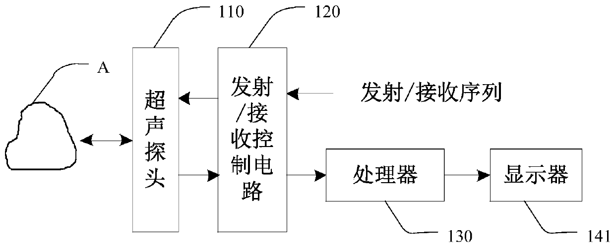
[0064] The present invention will be further described in detail below through specific embodiments in conjunction with the accompanying drawings. Wherein, similar elements in different implementations adopt associated similar element numbers. In the following implementation manners, many details are described for better understanding of the present application. However, those skilled in the art can readily recognize that some of the features can be omitted in different situations, or can be replaced by other elements, materials, and methods. In some cases, some operations related to the application are not shown or described in the description, this is to avoid the core part of the application being overwhelmed by too many descriptions, and for those skilled in the art, it is necessary to describe these operations in detail Relevant operations are not necessary, and they can fully understand the relevant operations according to the description in the specification and genera...


PUM


Abstract

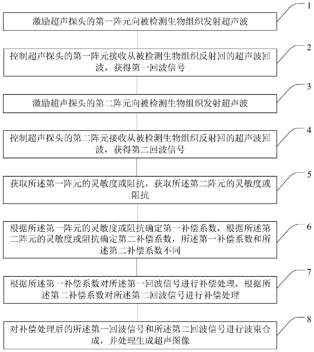
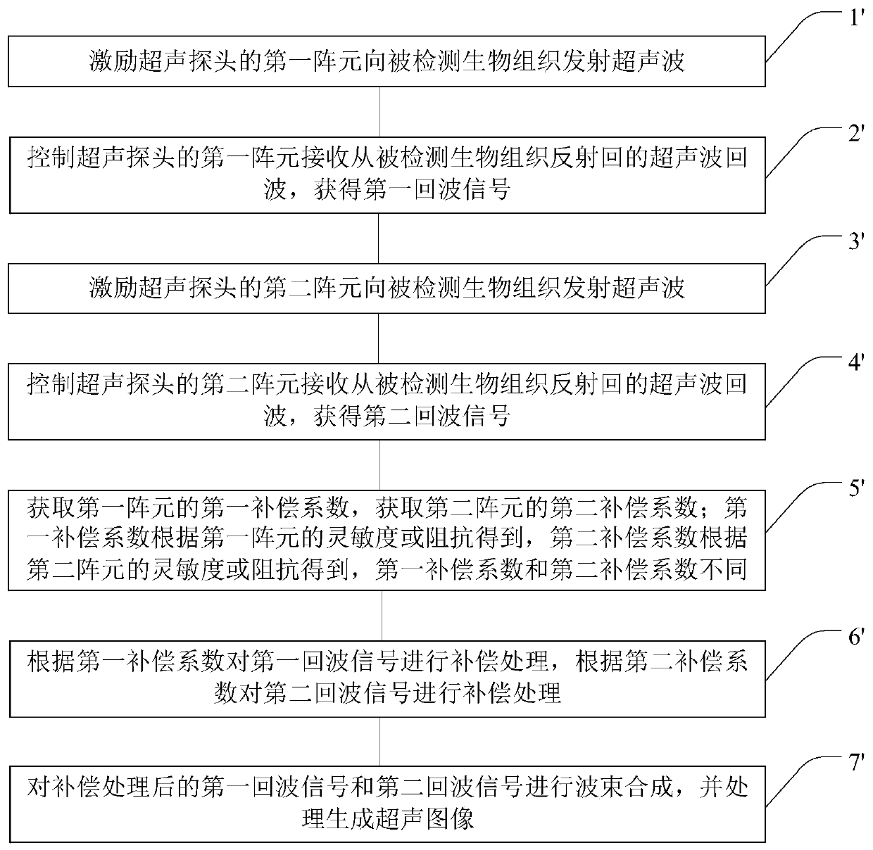
The invention provides ultrasonic diagnostic equipment and an ultrasonic imaging method. By obtaining first array element sensitivity or impedance, second array element sensitivity or impedance is acquired; according to the first array element sensitivity or impedance, a first compensation coefficient is determined, and according to the second array element sensitivity or impedance, a second compensation coefficient is determined, wherein the first compensation coefficient is different from the second compensation coefficient; compensation processing is carried out on a first echo signal according to the first compensation coefficient, and compensation processing is carried out on a second echo signal according to the second compensation coefficient; and the first eco signal and the secondeco signal after compensation treatment are subjected to beam synthesis, and are processed to generate an ultrasonic image. Corresponding compensation coefficients are determined according to the sensitivity or impedance of the respective array elements, then the eco signals generated by the respective array elements are compensated to reduce sensitivity or impedance difference between differentarray elements, and space consistency and uniformity of images are improved, thereby improving the final ultrasonic image display effect.

Description

technical field [0001] The invention relates to the field of ultrasonic imaging, in particular to ultrasonic diagnostic equipment and an ultrasonic imaging method. Background technique [0002] Medical ultrasonic imaging diagnostic equipment uses the propagation of ultrasonic waves in the human body to obtain ultrasonic characteristic information of human tissue and organ structures. Current ultrasonic diagnostic systems usually use multi-element probes. In this system, high-voltage pulse waves are loaded on each array element of the probe, and the array elements are excited to generate high-frequency ultrasonic waves, which then form a transmission beam and enter the human body. Each array element of the probe receives the echo scattered or reflected by the human tissue structure, and through beam synthesis, the echo data from each point in the longitudinal direction to each array element are added in phase to form a receiving beam. After processing each receiving beam, a...

Claims


Application Information

Patent Timeline
Patent Type & Authority Applications(China)
IPC IPC(8): A61B8/00
CPCA61B8/4444A61B8/5207
Inventor 崔忠艺王永波覃东海阳光辉席光磊
Owner SHENZHEN MINDRAY BIO MEDICAL ELECTRONICS CO LTD
Why Eureka
Try Eureka