
Electric injection molding device for injection molding machine

An injection molding machine, electric technology, applied in the field of electric injection molding device, can solve the problems of high cost of injection device, easy deviation of lead screw angle, difficult adjustment of lead screw, etc.

Pending Publication Date: 2020-07-07
NINGBO ZHAFIR PLASTICS MACHINERY
View PDF0 Cites 0 Cited by
  • Summary
  • Abstract
  • Description
  • Claims
  • Application Information

AI Technical Summary

Problems solved by technology

These two systems use different power motors, separate actions, and have different bearing support units. The pre-molding and injection actions are realized by two sets of motors and two sets of bearings, and in the actual practical process, the angle of the screw is prone to deviation , this setting method makes the adjustment of the lead screw more difficult, and the cost of the injection device is higher, and the floor space is relatively large

Method used


Image

  • Electric injection molding device for injection molding machine
  • Electric injection molding device for injection molding machine

Examples


Embodiment Construction

[0024] The following are specific embodiments of the present invention and in conjunction with the accompanying drawings, the technical solutions of the present invention are further described, but the present invention is not limited to these embodiments.

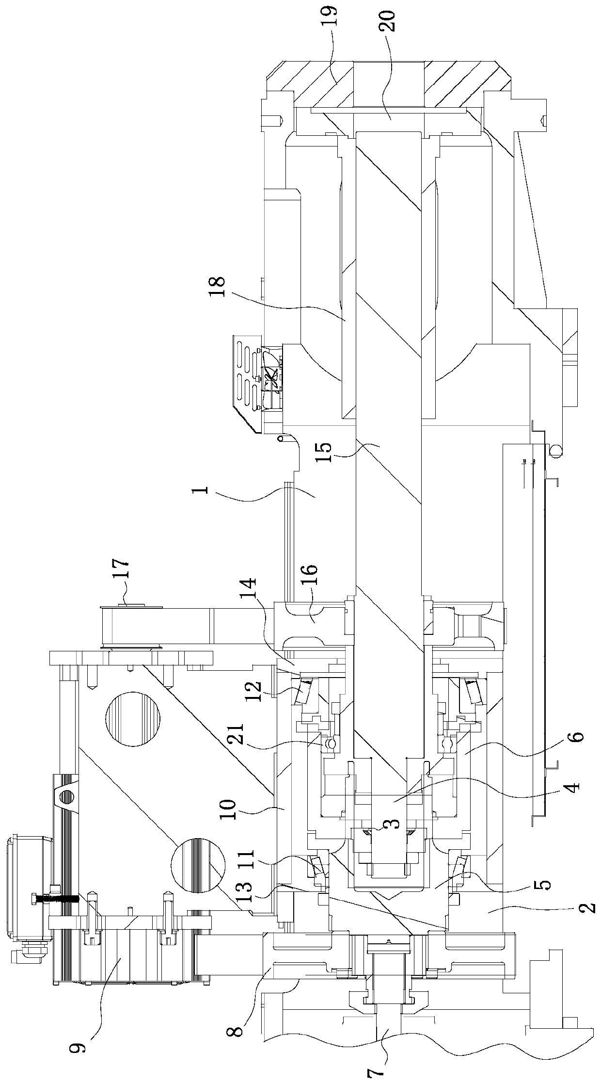
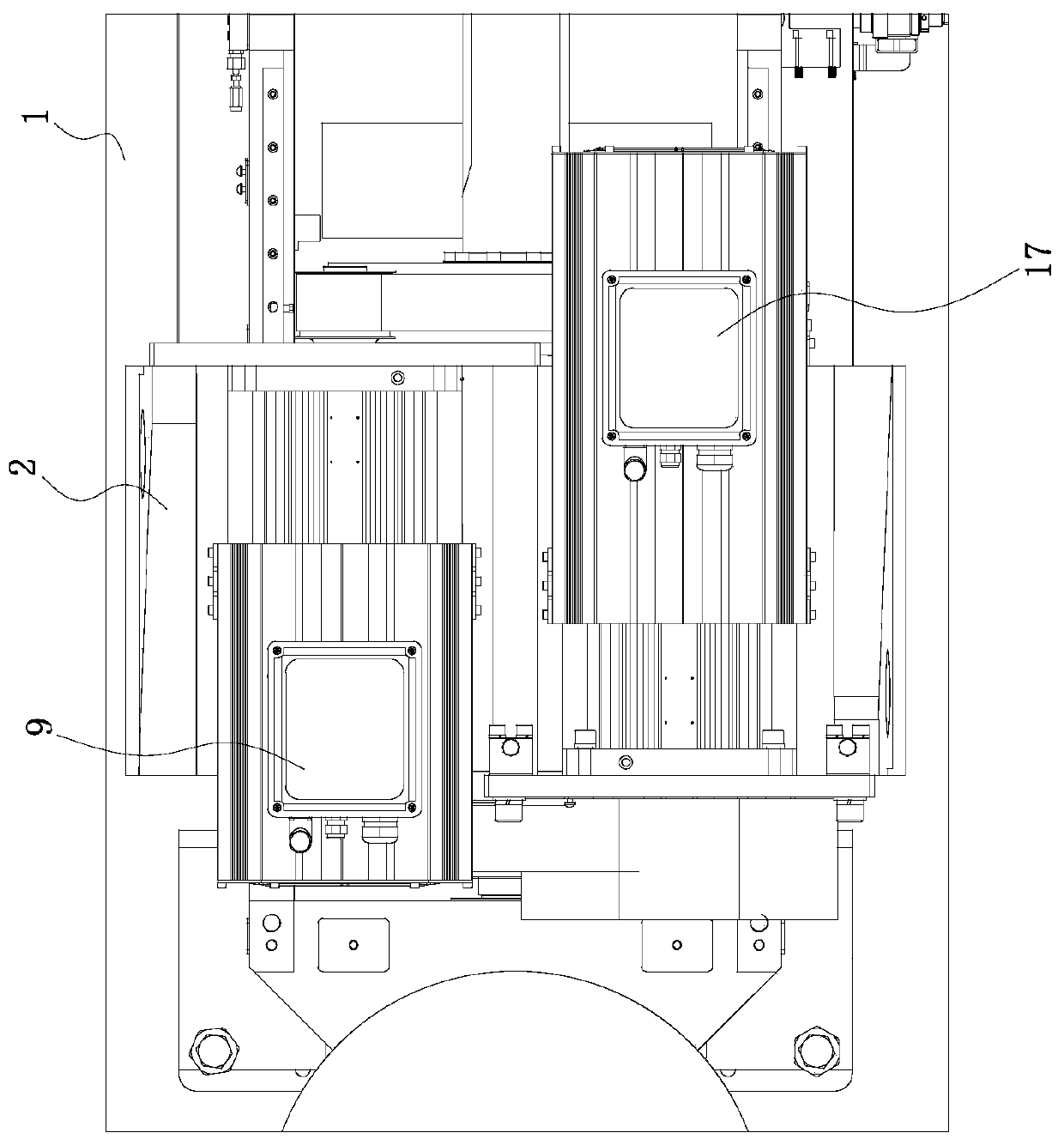
[0025] Such as figure 1 with figure 2 As shown, the electric injection molding device used for the injection molding machine includes: an injection seat 1, the upper end of which is slidingly connected with a pre-molded seat; Movable connection; screw assembly, which is threadedly connected with injection seat 1, connecting part 4 is provided at the end of the screw assembly, and self-aligning roller bearing 3 is arranged on connecting part 4, and self-aligning roller bearing 3 is inserted into the pre-molded bearing The outer side wall of the inner and spherical roller bearing 3 is connected with the inner side wall of the pre-molded bearing.

[0026] The pre-molding seat can move back and forth on the injection seat 1...


PUM


Abstract

The invention belongs to the field of injection molding machines, and particularly relates to an electric injection molding device for an injection molding machine. The electric injection molding device for the injection molding machine comprises an injection seat, a pre-plastic assembly and a screw assembly, wherein a pre-plastic seat is slidably connected to the upper end of the injection seat;a pre-plastic bearing is arranged on the end part of the pre-plastic assembly, the pre-plastic bearing is movably connected with a pre-plastic seat; one end of the screw assembly is connected with theinjection seat, a connecting part is arranged on the end part of the screw assembly, the connecting part is provided with a self-aligning roller bearing, and the self-aligning roller bearing is movably inserted in the pre-plastic bearing; and when the screw assembly rotates, the screw assembly can drive the pre-plastic bearing to move forward and backward relative to the injection seat. Comparedwith the prior art, The electric injection molding device for the injection molding machine has the advantages that the electric injection molding device used for the injection molding machine only requires the pre-plastic bearing to connect a screw and the pre-plastic assembly, the occupied space of the injection molding device is saved, and the number of the internal parts of the injection molding device is reduced, the cost is reduced, the screw separately relies on a deep groove ball bearing and the self-aligning roller bearings for centering and maintaining the screw angle to ensure thatthe screw angle does not shift, and the requirement of injection molding is met.

Description

technical field [0001] The invention belongs to the field of injection molding machines, and in particular relates to an electric injection molding device for injection molding machines. Background technique [0002] At present, all electric injection devices use a motor to drive the lead screw, which converts the rotational motion of the motor rotor into the linear feed motion of the relevant machinery, so as to realize the injection and ejection actions. The screw is provided with radial positioning support by the supporting bearing unit, and bears the axial injection and ejection force. The plasticizing function of the electric injection device is driven by the motor through the transmission device to rotate the screw. These two systems use different power motors, separate actions, and have different bearing support units. The pre-molding and injection actions are realized by two sets of motors and two sets of bearings, and in the actual practical process, the angle of t...

Claims


Application Information

Patent Timeline
Patent Type & Authority Applications(China)
IPC IPC(8): B29C45/17B29C45/50
CPCB29C45/1761B29C45/50B29C45/5008B29C2045/5012
Inventor 傅南红徐柯蒋超杰陈邦锋郭未已
Owner NINGBO ZHAFIR PLASTICS MACHINERY
Learn More