
Coaxial rotor wing control device

A control device and rotor technology, which is applied in the field of helicopter rotors, can solve the problems of small lift, increasing the space between the upper rotor and the lower rotor, and increasing the space occupied by the blades, etc.

Active Publication Date: 2020-07-07
深圳联合飞机科技有限公司
View PDF11 Cites 1 Cited by
  • Summary
  • Abstract
  • Description
  • Claims
  • Application Information

AI Technical Summary

Problems solved by technology

Since the above-mentioned space is small, the lift provided by the above-mentioned coaxial rotor control device is easy to be small. To increase the lift, it is necessary to increase the space formed by the upper rotor and the lower rotor.
In the prior art, the space formed by the upper rotor and the lower rotor is generally increased by increasing the arm length of the blade. However, increasing the arm length of the blade will increase the space occupied by the blade, which in turn makes the upper rotor and the lower rotor In order to avoid the occurrence of the above-mentioned situation of paddling, the distance between the upper rotor and the lower rotor is generally increased. However, the distance between the upper rotor and the lower rotor increases, which will make the helicopter Increased flight resistance

Method used


Image

  • Coaxial rotor wing control device
  • Coaxial rotor wing control device
  • Coaxial rotor wing control device

Examples


Embodiment Construction

[0084] The following will clearly and completely describe the technical solutions in the embodiments of the present invention with reference to the accompanying drawings in the embodiments of the present invention. Obviously, the described embodiments are only some, not all, embodiments of the present invention. Based on the embodiments of the present invention, all other embodiments obtained by persons of ordinary skill in the art without making creative efforts belong to the protection scope of the present invention.

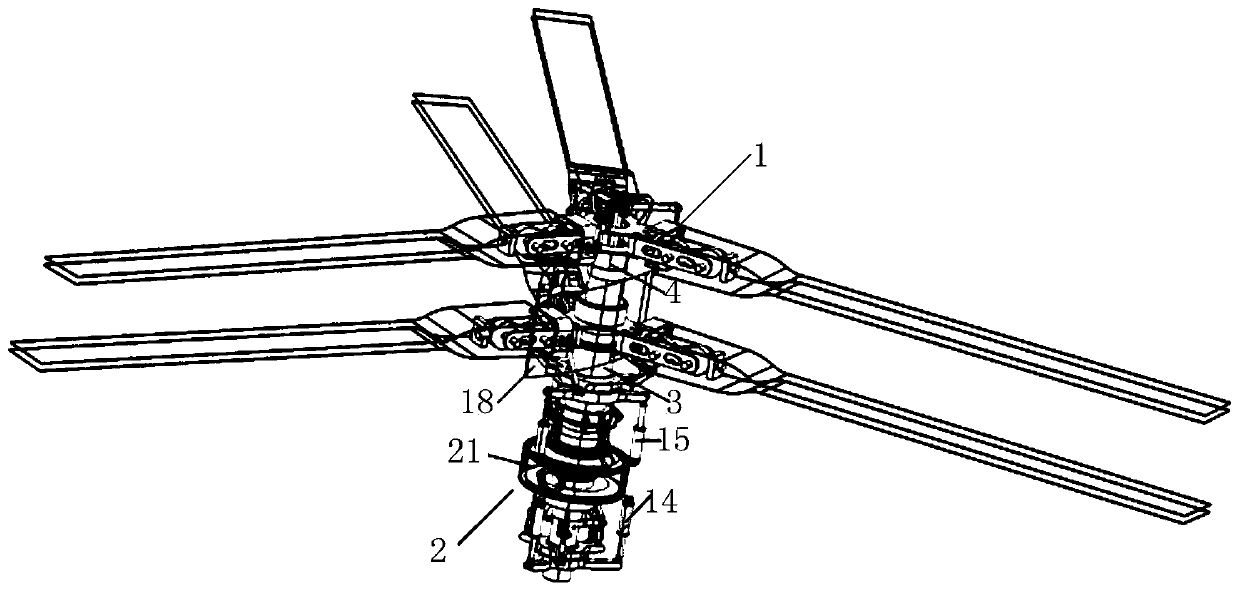
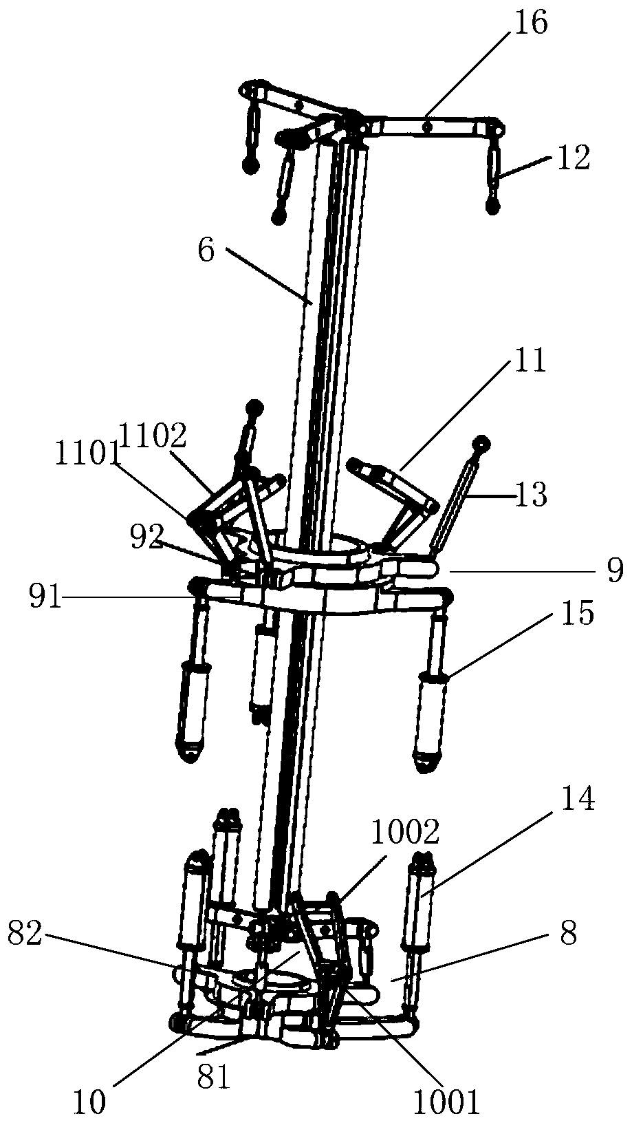
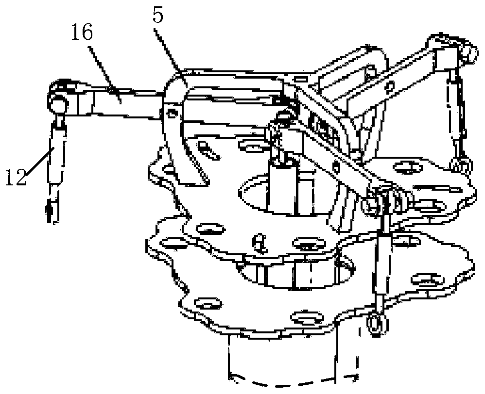
[0085] In order to solve the problems of the prior art, the embodiment of the present invention provides a coaxial rotor control device, the structural diagram of which is shown in Figure 1~4 As shown, the rotor control device includes: gearbox 2, outer shaft 3, inner shaft 4, inner shaft head frame 5, transmission shaft 6, connecting rod 7, first swash plate 8, second swash plate 9, first Anti-twist arm 10, second anti-twist arm 11, first pull rod 12, second...


PUM


Abstract

The embodiment of the invention provides a coaxial rotor wing control device. The output end of a gearbox of the device sleeves an outer shaft and an inner shaft separately, and the outer shaft is hinged to the inner shaft and sleeved with a second swash plate-stator and a second swash plate-rotor; and a transmission shaft is placed in the inner shaft, and an inner shaft head frame is fixedly installed on the end face of the inner shaft and hinged to the second turning rod. The transmission shaft is respectively hinged with the first turning rod and the second turning rod, the first turning rod is respectively hinged with the first pull rod and the inner shaft head frame, the connecting rod is movably hinged with the first tilting tray, the first tilting tray is hinged to the first steering engine and the first anti-torque arm, the first steering engine is hinged to the outer side wall of the gearbox, the gearbox is hinged to the second steering engine, the second steering engine is fixedly hinged with the second tilting tray, the second tilting tray-stator is hinged with the second anti-torsion arm, and the movable outer side wall of the second inclined disc is hinged to one end of a second pull rod. According to the device provided by the invention, the lifting force can be increased under the condition that the space occupied by the blades is not changed.

Description

technical field [0001] The invention relates to the technical field of helicopter rotors, in particular to a coaxial rotor control device. Background technique [0002] Single-rotor helicopters rely on the tail rotor for balance and steering. Compared with single-rotor helicopters, coaxial helicopters perform heading control and balance through the difference between the upper and lower rotors. Due to the compact structure and good maneuverability of coaxial helicopters, Therefore, it has a wide range of applications. [0003] Coaxial helicopters generally achieve heading control and balance by controlling the change of rotor pitch and coordinating the balance relationship between the two rotors during flight. In the prior art, a coaxial helicopter has a coaxial rotor control device, and the coaxial helicopter generally controls the pitch between the blades through the coaxial rotor control device. [0004] Although the pitch between the blades can be controlled by the abo...

Claims


Application Information

Patent Timeline
Patent Type & Authority Applications(China)
IPC IPC(8): B64C27/10B64C27/46B64C27/59B64C27/72
CPCB64C27/10B64C27/46B64C27/59B64C27/72
Inventor 孙万霍亚东田刚印杨世涛
Owner 深圳联合飞机科技有限公司
Learn More