
Small garbage treatment transfer station

A technology of garbage disposal and transfer station, which is applied in the direction of garbage transmission, garbage collection, loading/unloading, etc., and can solve the problems of destroying social harmony, inability to realize fast feeding and discharging, inability to effectively compress and collect garbage, etc.

Active Publication Date: 2020-07-07
广州市绿河环保设备有限公司
View PDF7 Cites 0 Cited by
  • Summary
  • Abstract
  • Description
  • Claims
  • Application Information

AI Technical Summary

Problems solved by technology

[0002] Garbage is solid waste generated in human daily life and production. Due to the large amount of discharge, complex and diverse components, and polluting, resourceful and social nature, it needs harmless, resourceful, reduction and socialized treatment. If it is not handled properly, it will pollute the environment, affect environmental sanitation, waste resources, destroy the safety of production and life, and disrupt social harmony. Garbage disposal is to quickly remove garbage, conduct harmless treatment, and finally make reasonable use of it. Applied waste disposal methods are sanitary landfill, high-temperature composting and incineration. The purpose of waste disposal is harmlessness, resource utilization and reduction. The waste disposal transfer station is an important method for waste disposal and storage. In the prior art, waste The processing transfer station cannot realize fast feeding and discharging, and cannot effectively compress and collect the sorted and processed garbage, resulting in low processing efficiency, and cannot realize thorough photolysis and adsorption of odor treatment, and the deodorization mechanism is not easy to replace and maintain. And it cannot realize the normal circulation of internal and external air, and cannot meet the needs of use. Therefore, the realization of a small garbage disposal transfer station that can solve such problems is imperative

Method used


Image

  • Small garbage treatment transfer station
  • Small garbage treatment transfer station
  • Small garbage treatment transfer station

Examples


Embodiment 1

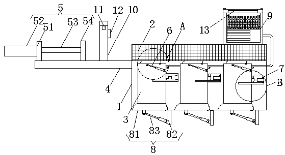
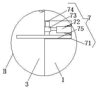
[0023] Embodiment 1: A small-scale garbage processing transfer station, including a processor body 1, a classification push mechanism 5, an inlet mechanism 6, a compression mechanism 7, a discharge mechanism 8, and a deodorization and ventilation mechanism 9, and the processor body 1 provides a mechanism and The installation place of the device, the upper wall of the processor body 1 is provided with a strip groove 2, the strip groove 2 is convenient for pushing the garbage, and the inside of the processor body 1 is uniformly equipped with a processing chamber 3 to realize the storage of garbage, and the processor The upper end of the left wall of the body 1 is provided with a support plate 4, which provides a support and installation platform, the upper surface of the support plate 4 is flat with the bottom surface of the strip groove 2, and the classification push mechanism 5 is correspondingly arranged on the upper wall of the support plate 4 On the left side, inlet mechanis...

Embodiment 2

[0027] The difference between this embodiment and Embodiment 1 is:

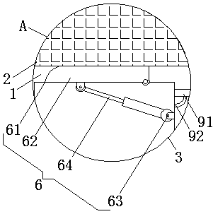
[0028] In this embodiment, the classification push mechanism 5 includes a vertical plate 51, a hydraulic pump 52, a telescopic column 53 and a material pushing plate 54. Fixedly connected in the wall installation port of the vertical plate 51, the hydraulic oil output port of the hydraulic pump 52 communicates with the oil inlet port of the telescopic column 53, the pusher plate 54 is arranged on the right part of the telescopic end of the telescopic column 53, and the inlet mechanism 6 includes an inlet 61. The inlet sealing plate 62, the U-shaped plate 63 and the electric telescopic rod 64, the inlet 61 is respectively arranged on the top wall of the processing chamber 3, and all communicate with the strip groove 2, and the right end of the inlet sealing plate 62 is hinged by a hinge On the right wall of the entrance 61, and corresponding to the entrance 61, the U-shaped plates 63 are respectively arranged ...

Embodiment 3

[0031] The difference between this embodiment and Embodiment 1 is:

[0032] In the present embodiment, the deodorizing and ventilating mechanism 9 includes a main ventilation cavity 91, a branch pipe 92, a deodorizing box 93, a UV ultraviolet tube 94, a fixed leak plate 95, a fixed screw 96, a movable leak press plate 97 and activated carbon The small ball 98 and the ventilation main cavity 91 are arranged inside the processor body 1, the air port of the ventilation main cavity 91 is connected with the corresponding processing cavity 3 gas ports through the branch pipe 92, and the deodorization box 93 is arranged on the processor body 1. On the upper wall, the upper end of the deodorization box 93 is an opening mechanism, and the ventilation opening at the bottom of the side wall of the deodorization box 93 is connected to the ventilation opening of the ventilation main cavity 91 through a conduit, and the UV ultraviolet tubes 94 are installed in the deodorization box respectiv...


PUM


Abstract

The invention discloses a small garbage treatment transfer station, which comprises a treater body, a classified pushing mechanism, inlet mechanisms, compression mechanisms, discharging mechanisms anda deodorizing and ventilating mechanism. A strip-shaped groove is formed in the upper wall of the treater body, treatment cavities are evenly formed inside the treater body, a supporting plate is arranged at the upper end of the left end wall of the treater body, the classified pushing mechanism is correspondingly arranged on the left side of the upper wall face of the supporting plate, the inletmechanisms are arranged on the top walls of the treatment cavities correspondingly and all communicate with the strip-shaped groove, and the compression mechanisms are arranged inside the treatment cavities correspondingly. According to the small garbage treatment transfer station, all the mechanisms are designed reasonably and are good in connectivity, garbage can be effectively classified, pushed and compressed to be collected, the treatment efficiency is improved, feeding inlets and discharging outlets can be quickly opened and closed according to the demand, thorough photolysis and odor adsorption treatment are achieved, the mechanisms are convenient to replace and maintain, and normal circulation of internal air and external air can be realized to meet the using demands.

Description

technical field [0001] The invention relates to the technical field of garbage treatment equipment, in particular to a small garbage treatment transfer station. Background technique [0002] Garbage is solid waste generated in human daily life and production. Due to the large amount of discharge, complex and diverse components, and polluting, resourceful and social nature, it needs harmless, resourceful, reduction and socialized treatment. If it is not handled properly, it will pollute the environment, affect environmental sanitation, waste resources, destroy the safety of production and life, and disrupt social harmony. Garbage disposal is to quickly remove garbage, conduct harmless treatment, and finally make reasonable use of it. Applied waste disposal methods are sanitary landfill, high-temperature composting and incineration. The purpose of waste disposal is harmlessness, resource utilization and reduction. The waste disposal transfer station is an important method for ...

Claims


Application Information

Patent Timeline
IPC IPC(8): B65F9/00
CPCB65F9/00
Inventor 林根
Owner 广州市绿河环保设备有限公司
Learn More