Deep roadway prestress full-anchor supporting construction equipment and construction method thereof

A technology of construction equipment and construction methods, applied in mining equipment, tunnels, tunnel linings, etc., can solve the problems of poor physical properties of surrounding rock, labor and material resources, and poor compactness

Active Publication Date: 2020-07-07
淮南东华欧科矿山支护设备有限责任公司
View PDF12 Cites 3 Cited by
  • Summary
  • Abstract
  • Description
  • Claims
  • Application Information

AI Technical Summary

Problems solved by technology

[0003] 1. The traditional temporary support method generally adopts measures such as hydraulic props and other pillar roofs to enable the construction to proceed. In the later stage, all temporary supports need to be dismantled, and the process is cumbersome and consumes manpower and material resources;
[0004] 2. The traditional grouting support method adopts the method of one-time grouting. Due to technical limitations, it is impossible to effectively inject all the grout into the long anchor hole. The section of the anchor rod and the anchor hole is empty, and the compactness is poor. The essence is short-distance and shallow anchor injection, resulting in poor anchoring effect;
[0005] 3. In addition, the traditional grouting support method only solidifies the anchor rod and the anchor hole as a whole, but there are still sections and cracks between the broken rock around the anchor rod and the anchor hole. The traditional method of support is difficult and the physical properties of the surrounding rock are poor.

Method used


Image

  • Deep roadway prestress full-anchor supporting construction equipment and construction method thereof
  • Deep roadway prestress full-anchor supporting construction equipment and construction method thereof
  • Deep roadway prestress full-anchor supporting construction equipment and construction method thereof

Examples


Embodiment Construction

[0040] The following will clearly and completely describe the technical solutions in the embodiments of the present invention with reference to the accompanying drawings in the embodiments of the present invention. Obviously, the described embodiments are only some, not all, embodiments of the present invention. Based on the embodiments of the present invention, all other embodiments obtained by persons of ordinary skill in the art without making creative efforts belong to the protection scope of the present invention.

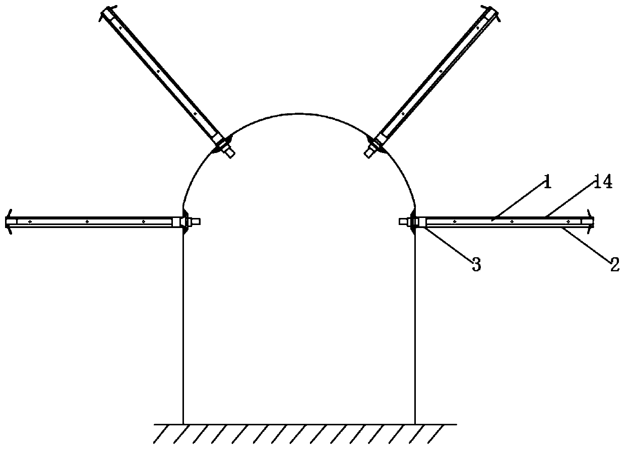
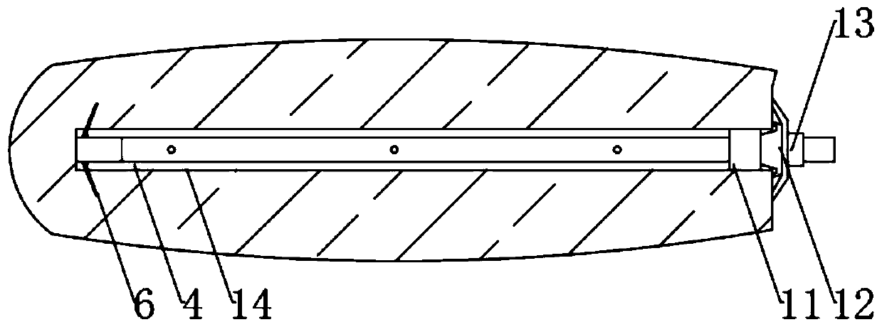
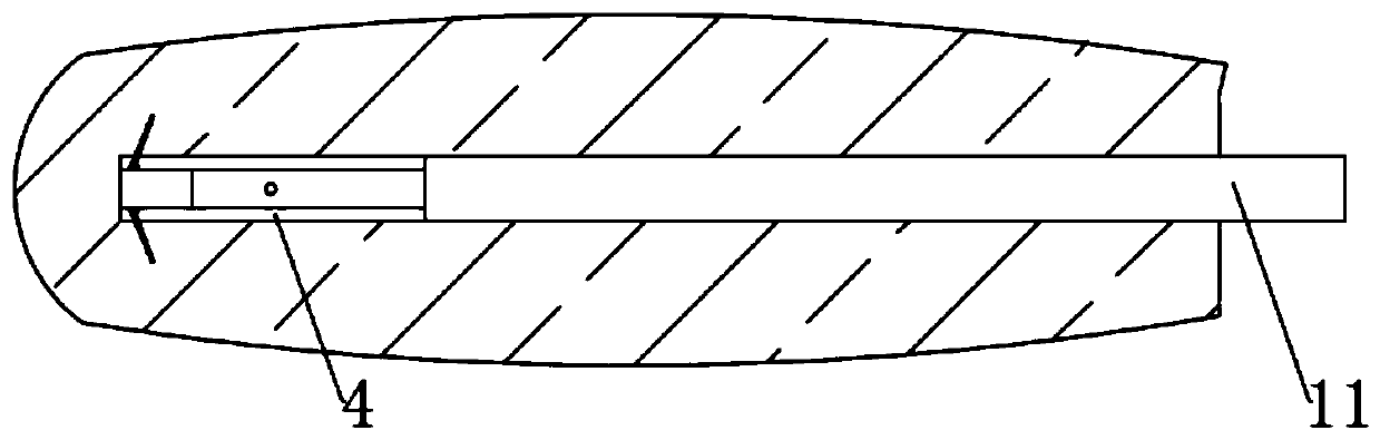
[0041] refer to Figure 1-5, a deep roadway prestressed full anchor support construction equipment provided by the present invention includes: a bolt 1 for inserting into the roadway anchor hole 14, a sprayer for providing primary slurry and secondary slurry to the bolt 1, and A pressure-holding pipeline for connecting the anchor rod 1 and the injection machine;

[0042] The anchor hole 14 has opposite inner ends 2 and outer ends 3, and the anchor rod 1 is co...


PUM


Abstract

The invention discloses deep roadway prestress full-anchor supporting construction equipment and a construction method thereof. The deep roadway prestress full-anchor supporting construction equipmentcomprises an anchor bolt for being inserted into a roadway anchor hole, an injection machine for providing primary grout and secondary grout for the anchor bolt, and a pressure maintaining pipeline for being connected with the anchor bolt and the injection machine. The anchor hole is provided with an inner end and an outer end opposite to the inner end, the anchor bolt is coaxially inserted intothe anchor hole, and the anchor bolt is provided with a first end and a second end opposite to the first end. After the anchor bolt is coaxially inserted into the anchor hole, the first end is locatedat the inner end, and the second end is located at the outer end. An injection clearance exists between the periphery of the anchor bolt and the anchor bolt, and the injection clearance at the innerend of the anchor holt is used for allowing the first grout to be injected into, so that the first end of the anchor bolt is anchored; and the injection clearance at the other positions of the anchorhole is used for allowing the secondary grout to be injected into, so that the anchor bolt is anchored in the whole length direction. And a layered grouting manner is adopted, so that the more than 90% of the clearance in the anchor holt is filled with the grout, the compactness is high, and whole-length anchoring of the anchor bolt is achieved.

Description

technical field [0001] The invention relates to the technical field of roadway support, in particular to construction equipment and a construction method for deep roadway prestressed full-anchor support. Background technique [0002] At present, in the support of underground roadways, the comprehensive method of anchor net, bolt and grouting is mostly used to realize the support of the roadway. The support operations include: temporary support, grouting support, etc., in the prior art , the bolt support process has the following disadvantages: [0003] 1. The traditional temporary support method generally adopts measures such as hydraulic props and other pillar roofs to enable the construction to proceed. In the later stage, all temporary supports need to be dismantled, and the process is cumbersome and consumes manpower and material resources; [0004] 2. The traditional grouting support method adopts the method of one-time grouting. Due to technical limitations, it is imp...

Claims


Application Information

Patent Timeline
IPC IPC(8): E21D20/02E21D21/00E21D11/00C04B28/06C04B111/70
CPCC04B28/06C04B2111/00724C04B2111/70C04B2201/50E21D11/00E21D20/021E21D20/025E21D20/028E21D21/0026C04B18/146C04B18/141C04B2103/302C04B2103/0068
Inventor 张辉
Owner 淮南东华欧科矿山支护设备有限责任公司
Why Eureka
Try Eureka