
Turbine rotor blade groove-type blade tip structure and design method thereof

A turbine rotor and groove-shaped technology, which is applied to the supporting elements of blades, mechanical equipment, engine elements, etc., can solve the problems of increasing the cost of the engine, reducing the working ability of the blades, and considering little strength and reliability.

Active Publication Date: 2020-07-07
AECC SHENYANG ENGINE RES INST
View PDF3 Cites 2 Cited by
  • Summary
  • Abstract
  • Description
  • Claims
  • Application Information

AI Technical Summary

Problems solved by technology

[0003] The groove-shaped blade tip of the turbine rotor blade is a cantilever structure. The blade tip of the existing blade is mainly designed based on performance requirements, and there is little consideration in terms of strength and reliability. At present, there is no specific control principle for the structural parameters of the blade tip, resulting in Often the depth of the blade tip groove is too large, the thickness of the blade tip wall is relatively thin, and the rounding radius between the blade tip wall and the roof is too small
Although the blade tip in the prior art can guarantee the short-term working performance of the blade, due to the insufficient strength margin of the blade tip wall and the excessive concentration of stress at the joint between the blade tip wall and the roof, it cannot cope with the changes in the position of the blade tip under normal working conditions. Temperature and stress lead to damages such as falling blocks of the blade tip enclosure wall; at the same time, because the blade tip pressure surface is subjected to a greater load than the suction surface, the equal blade tip enclosure wall thickness also leads to more serious damage on the blade tip pressure surface side
It reduces the reliability of the blades, and at the same time brings the problems of reduced blade working ability and high replacement rate, which increases the cost of the engine

Method used


Image

  • Turbine rotor blade groove-type blade tip structure and design method thereof
  • Turbine rotor blade groove-type blade tip structure and design method thereof
  • Turbine rotor blade groove-type blade tip structure and design method thereof

Examples


Embodiment Construction

[0030] In order to make the purpose, technical solution and advantages of the application more clear, the technical solution in the embodiment of the application will be described in more detail below in conjunction with the drawings in the embodiment of the application. In the drawings, the same or similar reference numerals denote the same or similar elements or elements having the same or similar functions throughout. The described embodiments are some, but not all, embodiments of the application. The embodiments described below by referring to the figures are exemplary, and are intended to explain the present application, and should not be construed as limiting the present application. Based on the embodiments in this application, all other embodiments obtained by persons of ordinary skill in the art without creative efforts fall within the protection scope of this application. Embodiments of the present application will be described in detail below in conjunction with th...


PUM


Abstract

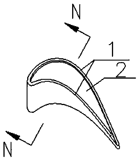
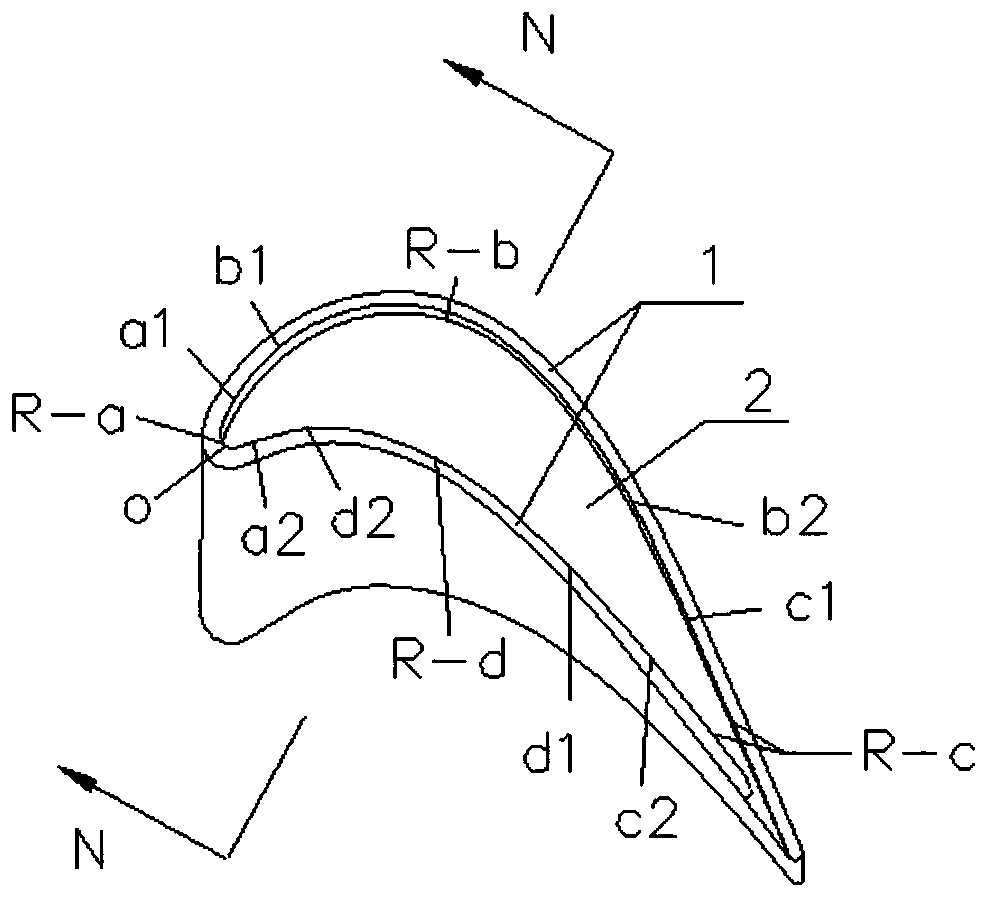
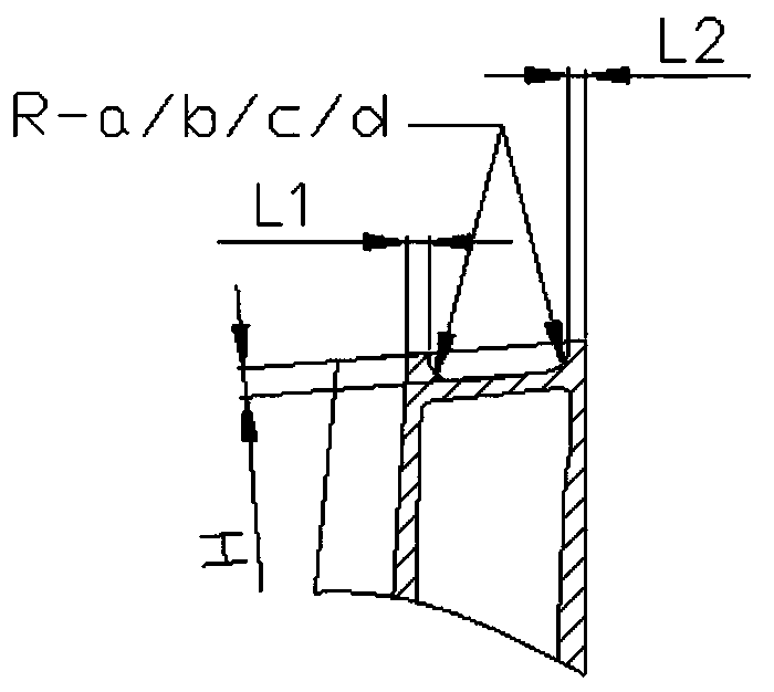
The invention belongs to the field of aero-engine blades, and particularly relates to a turbine rotor blade groove-type blade tip structure and a design method thereof. The turbine rotor blade groove-type blade tip structure comprises a top cover (2) and a blade tip fence (1), wherein the top cover (2) is arranged at the top of a turbine rotor blade, and the blade tip fence (1) is arranged aroundthe top cover (2); the blade tip fence (1) comprises a pressure surface blade tip fence and a suction surface blade tip fence, and the wall thickness L1 of the pressure surface blade tip fence is larger than the wall thickness L2 of the suction surface blade tip fence; the top cover (2) and the blade tip fence (1) form a blade tip groove; and a variable radius fillet is arranged between the bladetip fence (1) and the top cover (2). According to the turbine rotor blade groove-type blade tip structure, the strength of the blade tip fence is improved, and the oversized cantilever size of the blade tip fence is avoided, so that the strength margin of the corresponding position is improved, a stress concentration effect is relieved, the service life of a blade is prolonged, the cost caused byparts replacement is reduced, and the design reliability is improved.

Description

technical field [0001] The application belongs to the field of aeroengine blades, in particular to a turbine rotor blade groove-shaped blade top structure and a design method thereof. Background technique [0002] In order to reduce the loss of aerodynamic performance caused by the top clearance of the turbine rotor blades of the gas turbine, it is necessary to control the flow of the leakage gas. [0003] The groove-shaped blade tip of the turbine rotor blade is a cantilever structure. The blade tip of the existing blade is mainly designed based on performance requirements, and there is little consideration in terms of strength and reliability. At present, there is no specific control principle for the structural parameters of the blade tip, resulting in Often the depth of the blade tip groove is too large, the thickness of the blade tip wall is relatively thin, and the rounding radius between the blade tip wall and the top cover is relatively small. Although the blade tip...

Claims


Application Information

Patent Timeline
Patent Type & Authority Applications(China)
IPC IPC(8): F01D5/14
CPCF01D5/147F01D5/141
Inventor 孙启超张志强张涛
Owner AECC SHENYANG ENGINE RES INST
Learn More