Dielectric filter, communication equipment, method for preparing dielectric block and method for preparing dielectric filter

A dielectric filter and communication equipment technology, applied in the communication field, can solve problems such as coupling influence and poor coupling effect

Inactive Publication Date: 2020-07-07
ANHUI TATFOOK TECH CO LTD
View PDF7 Cites 0 Cited by
  • Summary
  • Abstract
  • Description
  • Claims
  • Application Information

AI Technical Summary

Problems solved by technology

In order to realize the coupling between the adjacently arranged dielectric resonators in the existing dielectric filters, usually when the surface of the dielectric resonator is metallized, a window is formed on the surface of the dielectric resonator (that is, not Metallization, exposing the part of the dielectric body), the coupling between the adjacent dielectric resonators is realized through this window, but the window contains air, which has a great relationship with the dielectric constant of the dielectric body of the dielectric resonator. difference, causing the coupling through this window to be affected, and the coupling effect is not good

Method used


Image

  • Dielectric filter, communication equipment, method for preparing dielectric block and method for preparing dielectric filter
  • Dielectric filter, communication equipment, method for preparing dielectric block and method for preparing dielectric filter
  • Dielectric filter, communication equipment, method for preparing dielectric block and method for preparing dielectric filter

Examples


Embodiment Construction

[0025] The application will be described in further detail below in conjunction with the accompanying drawings and embodiments. In particular, the following examples are only used to illustrate the present application, but not to limit the scope of the present application. Likewise, the following embodiments are only some of the embodiments of the present application but not all of them, and all other embodiments obtained by those skilled in the art without creative efforts fall within the protection scope of the present application.

[0026] The terms "first", "second", "third", "fourth", etc. (if any) in the specification and claims of this application and the above drawings are used to distinguish similar objects, and not necessarily Used to describe a specific sequence or sequence. It is to be understood that the data so used are interchangeable under appropriate circumstances such that the embodiments of the application described herein, for example, can be practiced in ...


PUM

PropertyMeasurementUnit
dielectric lossaaaaaaaaaa

Abstract

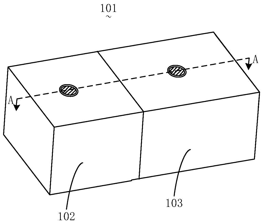
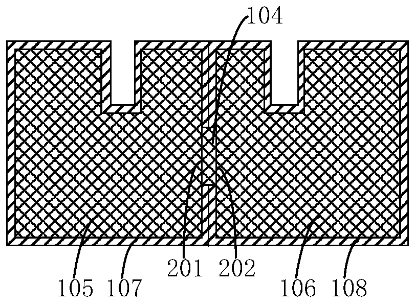
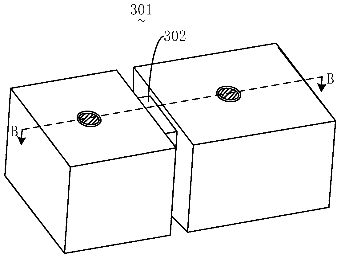
The invention discloses a dielectric filter, communication equipment, a method for preparing a dielectric block and a method for preparing the dielectric filter. The dielectric filter comprises a first dielectric resonator which at least comprises a first dielectric block; a second dielectric resonator which at least comprises a second dielectric block; a dielectric coupling plate which is arranged between the first dielectric block and the second dielectric block and connected with the first dielectric block and the second dielectric block, wherein the dielectric coupling plate is used for realizing coupling between the first dielectric resonator and the second dielectric resonator, and materials of the dielectric filter at least comprise strontium carbonate, samarium trioxide, aluminum oxide and titanium dioxide. According to the embodiment of the invention, the electromagnetic signal coupling effect of the dielectric filter can be improved, interference is reduced, and the performance can be optimized; and the dielectric filter provided by the embodiment of the invention has improved microwave dielectric properties.

Description

technical field [0001] The present application relates to the field of communication technology, in particular to a dielectric filter applied to a 5G communication system, a communication device, a method for preparing a dielectric block and a dielectric filter. Background technique [0002] With the rapid development of communication technology, especially the upcoming 5G communication era, more stringent technical requirements are put forward for the system architecture. While achieving high-efficiency and large-capacity communication, system modules must be highly integrated, miniaturized, Lightweight and low cost. For example, while 5G Massive MIMO technology realizes the further expansion of system channels from the current 8 or 16 channels to 32, 64 or even 128 channels, it requires that the overall system architecture size not be too large, and even a certain degree of miniaturization is required. Microwave filters are the core components of the system, and their per...

Claims


Application Information

Patent Timeline
Patent Type & Authority Applications(China)
IPC IPC(8): H01P1/20H01P7/10H01P11/00C04B35/01C04B35/63C04B35/622
CPCC04B35/01C04B35/622C04B35/6303C04B2235/3217C04B2235/3224C04B2235/3232H01P1/2002H01P7/105H01P11/007H01P11/008
Inventor 袁亮亮陆正武陈薛爱王健鹏吴亚辉吴文敬
Owner ANHUI TATFOOK TECH CO LTD
Why Eureka
Try Eureka