Reference signal determination method and device, electronic equipment and storage medium
A technology of reference signal and determination method, applied in the field of communication, can solve the problems of long UE wake-up time, increased system overhead, power consumption, etc.
- Summary
- Abstract
- Description
- Claims
- Application Information
AI Technical Summary
Problems solved by technology
Method used
Image
Examples
Embodiment 1
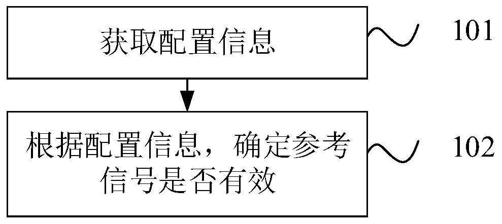
[0121] figure 2 It is a schematic flow chart of a method for determining a reference signal provided by an embodiment of the present application. The method can be executed by a device for determining a reference signal, and the device can be implemented by means of software and / or hardware. For example, the device can be a part of the above-mentioned user equipment or all of them, the method for determining the reference signal will be described below with the user equipment as the execution subject, such as figure 2 As shown, the method in the embodiment of the present application may include:
[0122] Step S101: Obtain configuration information.
[0123]The implementation method for the terminal to obtain the configuration information may be the configuration information sent by a network device such as a base station. The embodiment of the present application does not limit the specific implementation method for obtaining the configuration information and the specific c...
Embodiment 2
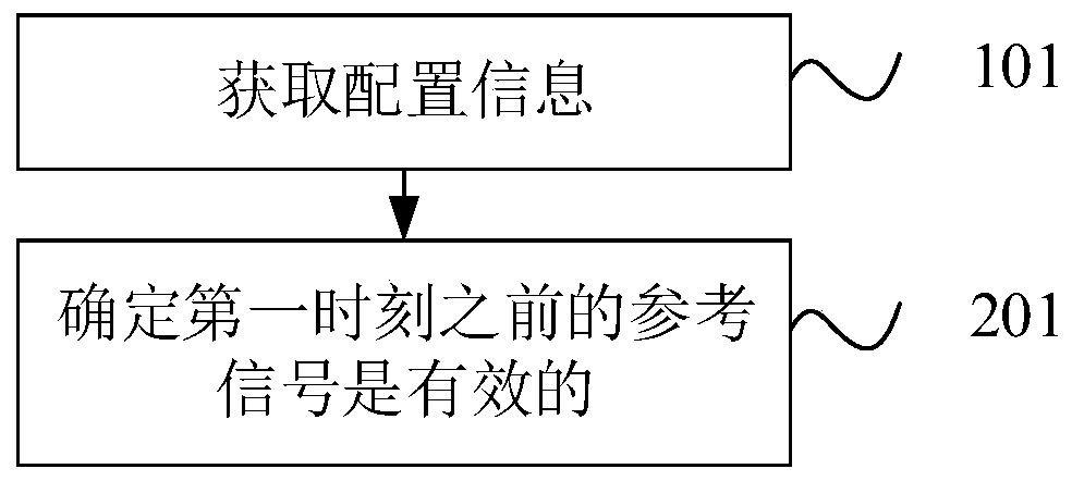
[0129] In one possible implementation, image 3 is a schematic flowchart of a method for determining a reference signal provided in another embodiment of the present application, the method may be executed by a device for determining a reference signal, and the device may be implemented by means of software and / or hardware, for example: the device may be the above-mentioned user equipment Part or all, the method for determining the reference signal will be described below with the user equipment as the execution subject, such as image 3 As shown, step S102 in the embodiment of this application may include:
[0130] Step S202: Determine that the reference signal before the first moment is valid.
[0131] Wherein, the first moment is: the moment when the paging opportunity PO starts or the PF starts or the first paging physical downlink control channel PDCCH listening opportunity starts, or the moment when the PO ends or the PF ends or the paging PDCCH listening opportunity en...
Embodiment 3
[0143] In one possible implementation, Figure 5 It is a schematic flow chart of a method for determining a reference signal provided in another embodiment of the present application. The method can be executed by a device for determining a reference signal, and the device can be implemented by means of software and / or hardware. For example, the device can be the above-mentioned user equipment Part or all, the method for determining the reference signal will be described below with the user equipment as the execution subject, such as Figure 5 As shown, step S102 in the embodiment of this application may include:
[0144] Step S301: Determine that the reference signal after the second moment is valid.
[0145] Wherein, the second moment is: a moment separated from the PO start or PF start or the first paging PDCCH listening opportunity by a third preset offset, or separated from the PO end or PF end or the paging PDCCH listening opportunity ending The moment of the fourth pr...
PUM
 Abstract
Description
Claims
Application Information
 - R&D
- Intellectual Property
- Life Sciences
- Materials
- Tech Scout
- Unparalleled Data Quality
- Higher Quality Content
- 60% Fewer Hallucinations
Browse by: Latest US Patents, China's latest patents, Technical Efficacy Thesaurus, Application Domain, Technology Topic, Popular Technical Reports.
© 2025 PatSnap. All rights reserved.Legal|Privacy policy|Modern Slavery Act Transparency Statement|Sitemap|About US| Contact US: help@patsnap.com


