Supercharge Your Innovation With Domain-Expert AI Agents!

Brush roller for textile printing and dyeing machinery

A technology of textile printing and dyeing, brush roller, applied in the processing of textile materials, textile processing machine accessories, printing and other directions, can solve the problems of inconvenient cleaning, inconvenient disassembly and replacement, etc., and achieve the effect of convenient cleaning and replacement, and convenient disassembly.

Pending Publication Date: 2020-07-10
义乌露真环保设备有限公司
View PDF6 Cites 0 Cited by
  • Summary
  • Abstract
  • Description
  • Claims
  • Application Information

AI Technical Summary

Problems solved by technology

[0003] However, it is inconvenient to disassemble and replace the brush filaments of the brush rollers used in textile printing and dyeing machinery at present, and it is inconvenient to clean

Method used


Image

  • Brush roller for textile printing and dyeing machinery
  • Brush roller for textile printing and dyeing machinery
  • Brush roller for textile printing and dyeing machinery

Examples


Embodiment Construction

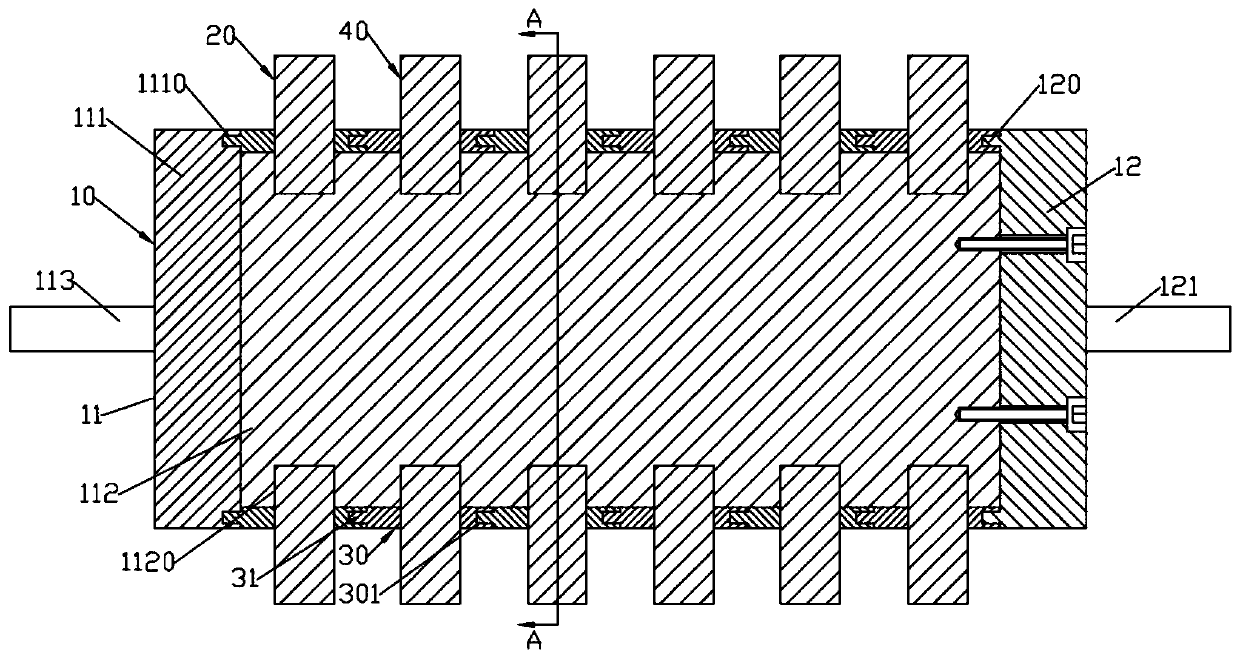
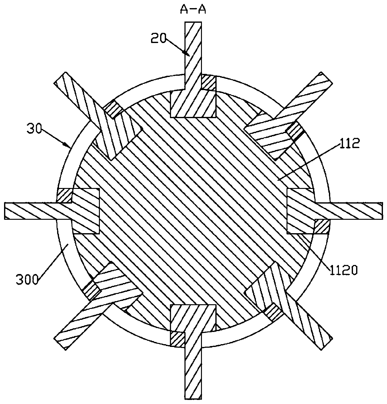
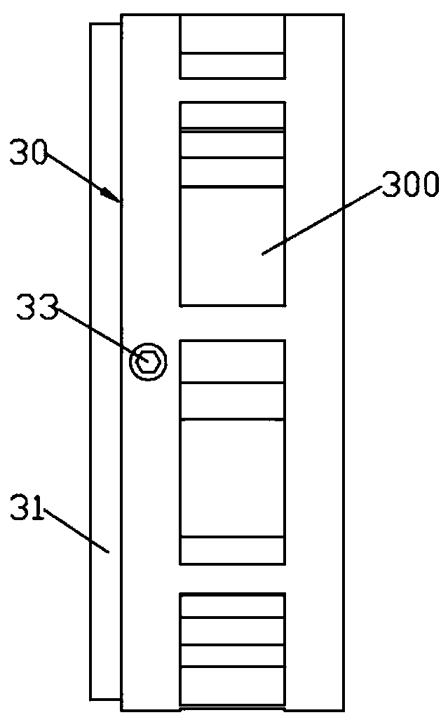
[0015] like Figure 1 ~ Figure 3 As shown, a brush roller for textile printing and dyeing machinery includes a central cylinder 10, a number of first bristle blocks 20, a number of annular cylinder-shaped stop rings 30 evenly distributed on the left and right, and a number of second bristle blocks 40; The central cylinder 10 includes a left central cylinder 11 and a right limit post 12; the left central cylinder 11 consists of a left limit post 111 and a center post 112 formed at the center of the right end face of the left limit post 111; 30 sets of stop rings Set and pivotally connected to the center column 112; the right limit column 12 is fixed on the right end surface of the center column 112 by several bolts; the center of the left end surface of the left limit column 111 is formed with a left metal column 113; the right limit column 12 A right metal column 121 is formed in the center of the right end face; a number of evenly distributed bristle block placement groove gr...


PUM


Abstract

The invention discloses a brush roller for textile printing and dyeing machinery. The brush roller comprises a central cylinder body, a plurality of first bristle blocks, a bristle block limiting device and a plurality of second bristle blocks. A bristle block placement groove group comprises a plurality of rectangular bristle block placement grooves which are circumferentially and uniformly distributed; and the first bristle blocks and the second bristle blocks are respectively inserted into different bristle block placement groove groups and are adjacently arranged left and right. The bristle block limiting device comprises a pair of circular-ring-cylinder-shaped side limiting rings which are arranged in a bilateral symmetry mode; and the pair of side limiting rings are arranged at the left end and the right end of the center cylinder in a sleeving mode and pivoted. A plurality of limiting strips which are circumferentially and uniformly distributed are arranged between the pair of side limiting rings in an arc sliding manner; a plurality of limiting grooves for limiting the first bristle blocks and the second bristle blocks are formed in the end faces of the same sides of the limiting strips in the rotating direction. The brush roller is convenient to disassemble, so that the first bristle blocks and the second bristle blocks are convenient to clean and replace.

Description

technical field [0001] The invention relates to the technical field of textile printing and dyeing machinery, in particular to a brush roller for textile printing and dyeing machinery. Background technique [0002] The brush roller is generally composed of a metal shaft, a bristle attachment (plastic tube, nylon tube, etc.), and a bristle. The processing procedures include: axle, casing (casting), eye picking, planting and flat wool. For special special-shaped brush rollers, if the planting of wool cannot be completed, the wool is planted by hand. The brush roller is suitable for 5 industries: food processing, glass ceramics industry, metal processing industry, polishing and cleaning industry, textile machinery. [0003] Yet at present, the brush filaments of the hair brush roller used in textile printing and dyeing machinery are damaged and inconvenient to disassemble and replace, and it is inconvenient to clean. Contents of the invention [0004] The object of the pre...

Claims


Application Information

Patent Timeline
IPC IPC(8): A46B7/04D06B23/02B41F17/00
CPCA46B7/04A46B2200/40B41F17/003D06B23/026
Inventor 王文卜
Owner 义乌露真环保设备有限公司
Features
  • R&D
  • Intellectual Property
  • Life Sciences
  • Materials
  • Tech Scout
  • Unparalleled Data Quality
  • Higher Quality Content
  • 60% Fewer Hallucinations
Learn More