Cleaning brush

A cleaning brush and cleaning technology, which is applied in the field of cleaning brushes, can solve problems such as inability to remove dust, inability to rotate bristles, and extensive dust removal and cleaning work, and achieve cleaning effects with labor-saving and good cleaning effects

Inactive Publication Date: 2020-07-10
NANYANG POWER SUPPLY COMPANY OF STATE GRID HENAN ELECTRIC POWER
View PDF10 Cites 2 Cited by
  • Summary
  • Abstract
  • Description
  • Claims
  • Application Information

AI Technical Summary

Problems solved by technology

[0002] Existing dust removal and cleaning work for information room equipment such as servers, switches, and security equipment is relatively extensive. Most of the information operation and maintenance personnel wipe the outer cover with a clean rag and then open it, and carry out dust removal and cleaning with an industrial hair dryer. The method is simple and easy to implement, but the dust removal effect is not good. The blown dust is easy to scatter into the air and fall to other equipment again. It does not have a substantial dust removal effect on all the equipment in the information room.
[0003] This dust removal method...

Method used


Image

  • Cleaning brush
  • Cleaning brush
  • Cleaning brush

Examples


Embodiment approach

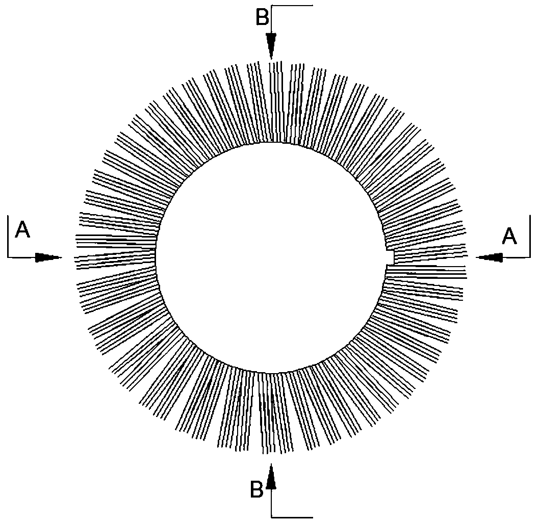
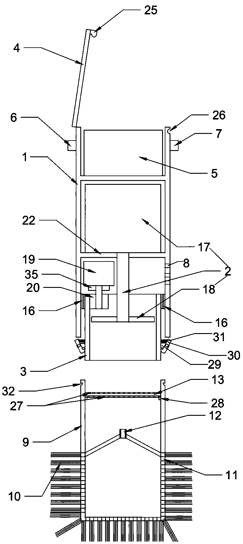
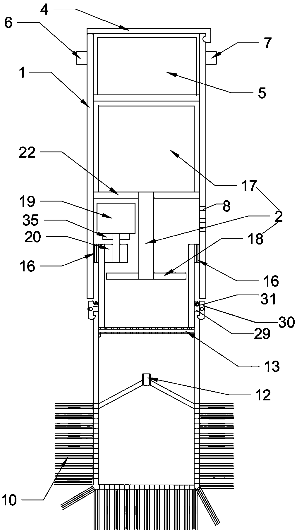
[0033] Such as Figure 1-4 Shown is the first embodiment of the present invention, a cleaning brush, including a control end and a cleaning end. The rotating cylinder 3 in 1, the fixed cylinder 1 is a circular shell structure, such as figure 2 As shown, the fixed cylinder 1 is provided with a circular partition 22 by injection molding, and the fan 2 is arranged on the partition 21. The fan 2 is composed of a motor 17 and a fan blade 18. The motor 17 is installed in the center of the partition 22 through bolts. , The through hole 1 that can pass through for the output shaft of the motor is punched out on the dividing plate 22 by a punching machine. The rotating cylinder 3 has a shell-like structure, and the top of the rotating cylinder 3 is fixed on the outside of the bearing 16 by glue, and the outer ring surface of the bearing 16 is fixed on the inner wall of the fixed cylinder 1 by glue. Free spins inside. In order to enable the rotating cylinder 3 to rotate automaticall...

Embodiment 2

[0037] Such as Figure 5 Shown is the second embodiment of the present invention, the difference between this embodiment and the first embodiment is that the cleaning end includes a connecting cylinder 14, the upper part of the connecting cylinder 14 is a cylindrical shell with both ends open, and the lower part is two ends open The circular frustum shell, the bottom end of the cylindrical shell and the larger end of the circular frustum shell are fixedly connected by glue, and the bottom end of the circular frustum shell is fixed with the vent pipe 15 by glue. The connection mode of cylinder 3 is identical with the connection mode of connection cylinder one 9 and rotating cylinder 3.

[0038] Install the connecting cylinder 2 14 on the rotating cylinder 3, and only turn on the switch 1 6 to make the fan 2 blow air downward. After the air enters through the air hole 1 8, it is blown downward by the fan 2, and then flows out from the ventilation pipe 15 to form The air flow bl...

Embodiment 3

[0040] Such as Figure 6 Shown is the third kind of embodiment of the present invention, and check valve 12 and strainer 13 are arranged inside rotating drum 2 3, and the arrangement mode of check valve 12 and strainer 13 is the same as embodiment one, and during use, first put The ventilation pipe 15 is bent to the required shape, and then the bolt 33 is screwed inward, so that the rubber pad is in close contact with the rotating cylinder 3 to prevent the rotating cylinder 3 from rotating, and then only the switch one 6 is turned on to make the fan 2 suck air upwards. The top of the filter screen 13 is a negative pressure, which forms the air flow from the air pipe 15 to the air hole one 8, and the mouth of the air pipe 15 can be aimed at the inside of the equipment to be cleaned, and the dust attached to the inside of the equipment is dedusted.


PUM


Abstract

The invention discloses a cleaning brush comprising a control end and a cleaning end. The control end comprises a fixed cylinder with openings in the two ends, a fan arranged in the fixed cylinder anda rotating cylinder rotationally connected into the fixed cylinder. A sealing cover is arranged at the top of the fixed cylinder; a driving device for driving the rotating cylinder to rotate and a power supply for providing power for the driving device and the fan are arranged in the fixed cylinder; a switch I for controlling the fan to rotate forwards or backwards and a switch II for controllingthe driving device to start or stop are arranged on the fixed cylinder; a first air hole is formed in the fixed cylinder, the cleaning end is detachably connected with the rotating cylinder, and an air hole communicated with the atmosphere is formed in the cleaning end. A user can adjust the mode of the fan and replace the cleaning end according to needs, so that the device can adapt to dust removal in various states and thoroughly and effectively treat dust inside and outside equipment.

Description

technical field [0001] The invention relates to the technical field of electric equipment, in particular to a cleaning brush. Background technique [0002] Existing dust removal and cleaning work for information room equipment such as servers, switches, and security equipment is relatively extensive. Most of the information operation and maintenance personnel wipe the outer cover with a clean rag and then open it, and carry out dust removal and cleaning with an industrial hair dryer. The method is simple and easy to implement, but the dust removal effect is not good. The dust blown up is easy to scatter into the air and fall to other equipment again. It does not have a substantial dust removal effect on all the equipment in the information room. [0003] This dust removal method can suck the dust into the handle to realize the thorough cleaning of the device shell and the accessible dust inside the device, but the bristles cannot be rotated, and the attached dust can only be...

Claims


Application Information

Patent Timeline
IPC IPC(8): A46B13/02A46B15/00A46B5/00
CPCA46B5/002A46B5/0095A46B13/02A46B15/00A46B15/0051A46B15/0053A46B2200/3026
Inventor 李华静张宛利刘向阳李瀚辰李华东张庶刘安波韩雪峰
Owner NANYANG POWER SUPPLY COMPANY OF STATE GRID HENAN ELECTRIC POWER
Why Eureka
Try Eureka