Mechanical arm and position adjusting method thereof
An adjustment method and technology of robotic arms, applied in the directions of manipulators, program-controlled manipulators, claw arms, etc., can solve the problems of many application scenarios of manipulators and insufficient degrees of freedom of manipulators to limit application scenarios, so as to reduce production costs and solve wiring problems. Problem, high precision effect
- Summary
- Abstract
- Description
- Claims
- Application Information
AI Technical Summary
Problems solved by technology
Method used
Image

Examples
Embodiment 1
[0039] Embodiment 1, in conjunction with attached Figure 1-4 Do the following description;
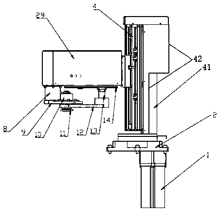
[0040] A mechanical arm in the embodiment of the present application includes an equipment base, a rotating device 2 arranged on the equipment base, a lifting device 4 arranged on the rotating device, and a terminal turning device arranged on the lifting device 4;
[0041] The lifting device 4 includes a linear guide rail one 16; a slide block 17 is arranged on the linear guide rail one 16;
[0042] The end turning device includes a lifting arm 6 fixedly connected to the slider 17; the upper end of the lifting arm 6 is provided with a servo motor reducer 7, and the output shaft 26 of the servo motor reducer 7 passes through the lifting arm 6 and is connected with the lifting arm 6. The lifting arm 6 is vertical; the output shaft 26 is equipped with a composite needle roller bearing 27; the output shaft 26 is provided with a compression nut 28; the composite needle roller bearing 27 i...
Embodiment 2
[0046] Embodiment 2, in conjunction with attached Figure 1-4 Do the following description;
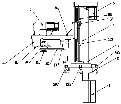
[0047] On the basis of Example 1, such as Figure 1-4 As shown, the rotating device 2 includes a rotating platform 2.1 arranged on the equipment base; the equipment base is provided with a servo motor 1 drivingly connected to the rotating platform 2.1.
[0048] Further, the lifting device 4 includes a rotating bracket 41, which is arranged on the rotating platform 21 and integrally linked with the rotating platform 21; the lifting frame 42 is arranged on the rotating bracket 41, and a servo is arranged on one side of the upper end of the lifting frame 42. Motor two 5, the output shaft of this servo motor two 5 is connected with synchronous pulley one; Ball screw 15 is installed in the described lift frame 18, and described linear guide rail one 16 is set on this ball screw 15; The upper end of the leading screw 15 is provided with a second synchronous pulley; the second synchronous ...
Embodiment 3
[0063] Embodiment 3, in conjunction with attached Figure 1-4 Do the following description;
[0064] On the basis of the conception of embodiments 1 and 2, a method for adjusting the position of a mechanical arm comprises the following steps:
[0065] Step 1. Install the grabbing device on the carrying platform, and connect the servo motor 1, servo motor 2, and servo motor reducer through the control computer;
[0066]Step 2: According to the predetermined position to be processed, control the computer to start the servo motor and then drive the rotating platform of the rotating device, so that the entire mechanical arm is adjusted on the horizontal plane until it reaches the predetermined position and then stops;
[0067] Step 3. After determining the horizontal position, preset the height position of the lifting arm, control the computer to start the servo motor 2 and then drive the ball screw to rotate to adjust the height of the lifting arm until it reaches the predetermi...
PUM
 Abstract
Description
Claims
Application Information