Supercharge Your Innovation With Domain-Expert AI Agents!

Differential rotary steering wheel of equipment loading and unloading vehicle

A technology for loading and unloading vehicles and equipment, which is applied to electric steering mechanisms, power steering mechanisms, steering mechanisms, etc., can solve problems such as increased friction, unfavorable steering, unfavorable roller steering, etc., to reduce power loss, realize clutching, and avoid tilting Effect

Pending Publication Date: 2020-07-10
YANCHENG FUDA NEW ENERGY CO LTD
View PDF0 Cites 0 Cited by
  • Summary
  • Abstract
  • Description
  • Claims
  • Application Information

AI Technical Summary

Problems solved by technology

[0002] At present, most of the loading and unloading operations of large-scale component equipment are completed by large-scale mobile hoisting machinery vehicles. Adjust the size of the supporting surface according to the needs, poor applicability and other defects, which make it impossible to complete the operations of component objects and heavy equipment loading and unloading trucks, which brings great difficulties to the enterprise, and the rotary wheel is the main part of the loading and unloading truck one
[0003] The traditional rotary wheel is driven by the drive motor to drive the rollers for transmission. When the ground is not stable, it is easy to cause power loss and increase friction, which is not conducive to the steering of the rollers. Due to the heavy weight of the loading and unloading truck, it is even more unfavorable for steering. And the existing loading and unloading The rotary wheel of the car cannot realize the clutch function, therefore, the present invention designs a differential rotary steering wheel of the equipment loading and unloading car to solve the problems existing in the prior art

Method used


Image

  • Differential rotary steering wheel of equipment loading and unloading vehicle
  • Differential rotary steering wheel of equipment loading and unloading vehicle
  • Differential rotary steering wheel of equipment loading and unloading vehicle

Examples


Embodiment Construction

[0021] The following will clearly and completely describe the technical solutions in the embodiments of the present invention with reference to the accompanying drawings in the embodiments of the present invention. Obviously, the described embodiments are only some, not all, embodiments of the present invention. Based on the embodiments of the present invention, all other embodiments obtained by persons of ordinary skill in the art without making creative efforts belong to the protection scope of the present invention.

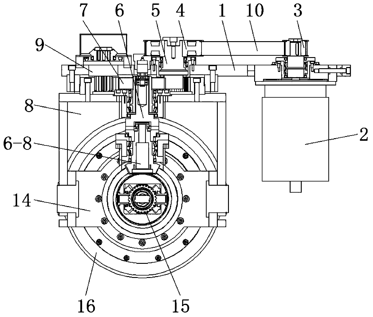
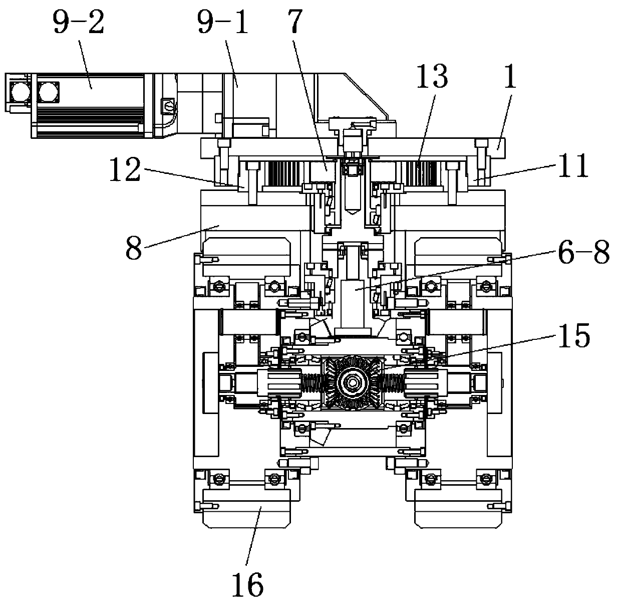
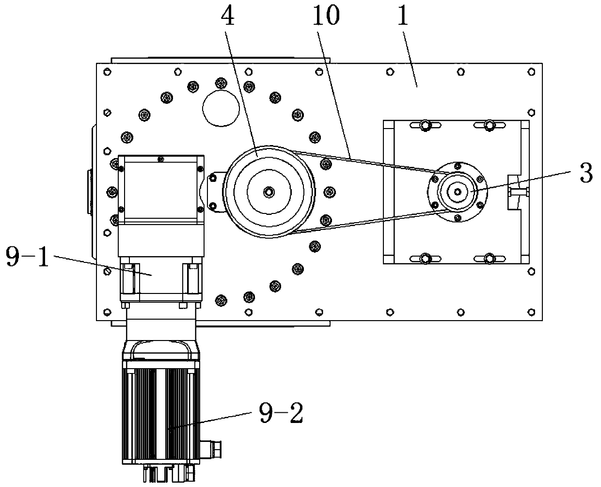
[0022] see Figure 1-8 , an embodiment provided by the present invention: a differential rotary steering wheel of an equipment loading and unloading vehicle, including a mounting plate 1, a drive motor 2 is installed at one end of the bottom of the mounting plate 1, and a driving wheel 3 is provided at the output end of the drive motor 2, The other end of mounting plate 1 top is provided with rotating shaft 5, and the top of rotating shaft 5 is provided with d...


PUM


Abstract

The invention discloses a differential rotary steering wheel of an equipment loading and unloading vehicle. The wheel comprises a mounting plate, a driving motor is mounted at one end of the bottom ofthe mounting plate; a driving wheel is arranged at the output end of the driving motor; a rotating shaft is arranged at the other end of the top of the mounting plate, a driven wheel is arranged at the top end of the rotating shaft, a transmission belt is arranged between the driving wheel and the driven wheel, a clutch structure is arranged at the bottom of the mounting plate, the mounting plateis connected with the rotating shaft, and a cylindrical gear is arranged at the top end of the outer side wall of the clutch structure. The differential rotary steering wheel is provided with the mounting plate, the driving motor, the driving wheel, the driven wheel, the rotating shaft and the cylindrical gear, the driving motor performs transmission through the driving wheel, the driven wheel and the transmission belt; the clutch structure is driven by the cylindrical gear to rotate, so that the wheel can be pushed linearly, and through a pin shaft and a rotary sleeve, in the advancing process, when two sets of rollers vibrate due to the uneven ground, the mounting framework conducts adaptive side inclination and swing, and inclination of the equipment body is avoided.

Description

technical field [0001] The invention relates to the technical field of differential wheels for loading and unloading vehicles, in particular to a differential rotary steering wheel for equipment loading and unloading vehicles. Background technique [0002] At present, most of the loading and unloading operations of large-scale component equipment are completed by large-scale mobile hoisting machinery vehicles. Adjust the size of the supporting surface according to the needs, poor applicability and other defects, which make it impossible to complete the operations of component objects and heavy equipment loading and unloading trucks, which brings great difficulties to the enterprise, and the rotary wheel is the main part of the loading and unloading truck one. [0003] The traditional rotary wheel is driven by the drive motor to drive the rollers for transmission. When the ground is not stable, it is easy to cause power loss and increase friction, which is not conducive to t...

Claims


Application Information

Patent Timeline
Patent Type & Authority Applications(China)
IPC IPC(8): B60K7/00B60K17/02B62D5/04
CPCB60K7/0007B60K17/02B62D5/0418B60K2007/0084
Inventor 许士东解学广成亭郑海北
Owner YANCHENG FUDA NEW ENERGY CO LTD
Features
  • R&D
  • Intellectual Property
  • Life Sciences
  • Materials
  • Tech Scout
  • Unparalleled Data Quality
  • Higher Quality Content
  • 60% Fewer Hallucinations
Learn More