Can fiber ribbon reading device and recognition method
A technology of a reading device and an identification method, which is applied to textiles and papermaking, etc., can solve the problems of inability to realize automatic identification of can fiber strips, increase costs, etc., and achieve the effect of reducing workload and improving production efficiency.
- Summary
- Abstract
- Description
- Claims
- Application Information
AI Technical Summary
Problems solved by technology
Method used
Image
Examples
Embodiment 1
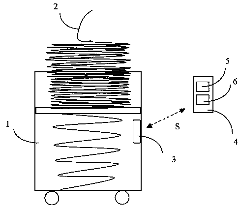
[0059] Such as figure 1 As shown, a can 1 with a fiber sliver 2 is provided with a can fiber sliver information storage unit 3 . During the fiber sliver production process of carding machine, drawing frame and combing machine, fiber sliver 2 is put into can 1 by ring. When the length of the fiber strip 2 in the can 1 reaches the preset length, the carding machine, draw frame or combing machine starts to change the can, and simultaneously the information of the fiber strip (in this embodiment, this information is Refer to the length of the fiber strip, the number of broken ends and the length of the fiber strip between the broken ends, etc.) into the fiber strip information storage unit 3.
[0060] The can fiber strip information storage part 3 is installed on the side wall of the can, and stores information such as the length of the fiber strip, the number of broken ends and the length of the fiber strip between the broken ends.
[0061] According to actual production condit...
Embodiment 2
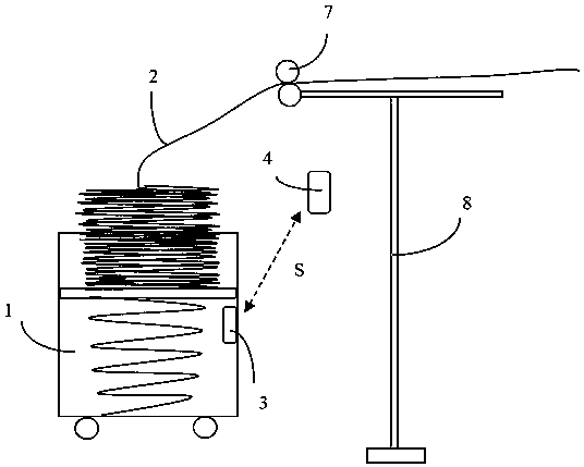
[0068] Such as figure 2 As shown, the can fiber strip reading device 4 is installed on a specific embodiment of the creel 8 .
[0069] In a draw frame, usually a maximum of 8 cans 1 are fed to the creel 8 for a single-head draw frame and a maximum of 16 cans 1 are fed to the creel 8 for a double-head draw frame. For the creel of the roving frame, up to 250 cans 1 are fed to the creel 8 . As shown, a can fiber strip reading device 4 is installed above a can 1 of the creel 8 . The can fiber strip reading device 4 reads the fiber strip information of the can fiber strip information storage part 3 in a non-contact manner. According to the read fiber sliver information, after calculation and analysis, the fiber sliver status information is transmitted to the equipment for the next step. The basic principle and method of reading and processing fiber sliver information are consistent with Embodiment 1.
[0070] Preferably, the creel 8 can share one or the can fiber sliver readin...
Embodiment 3
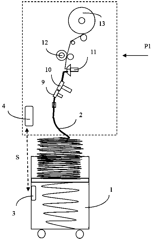
[0073] Such as image 3 As shown, the can fiber strip reading device 4 is installed at the spinning unit P1 of the rotor spinning machine. The fiber strips 2 of the can 1 enter the cotton feeding roller 9, and after being combed by the opening roller 10, the fiber strips 2 in a fiber state enter the rotor cup 11, and further, under the action of the high-speed rotating rotor cup 11, the fibers Through twisting, yarn is formed, and under the guide roller 12, it becomes a package 13.
[0074] The can fiber sliver reading device 4 is installed near the can 1 area of the spinning unit P1, communicates with the can fiber sliver information storage part 3, reads the information S, and calculates and analyzes according to the read fiber sliver information, Send the fiber sliver status information to the rotor spinning machine for the next step. The basic principle and method of reading and processing fiber sliver information are consistent with Embodiment 1.
PUM
 Abstract
Description
Claims
Application Information
 - R&D
- Intellectual Property
- Life Sciences
- Materials
- Tech Scout
- Unparalleled Data Quality
- Higher Quality Content
- 60% Fewer Hallucinations
Browse by: Latest US Patents, China's latest patents, Technical Efficacy Thesaurus, Application Domain, Technology Topic, Popular Technical Reports.
© 2025 PatSnap. All rights reserved.Legal|Privacy policy|Modern Slavery Act Transparency Statement|Sitemap|About US| Contact US: help@patsnap.com


