
Liquid supply type gas compression device

A technology of gas compression and gas booster pumps, which is applied in mechanical equipment, liquid fuel engines, liquid variable displacement machinery, etc. It can solve the problems of increasing the difficulty of oil pipe disassembly and oil spillage, so as to ensure smoothness and improve sealing performance , Improve the effect of clamping width

Inactive Publication Date: 2020-07-10
黄晓平
View PDF6 Cites 1 Cited by
  • Summary
  • Abstract
  • Description
  • Claims
  • Application Information

AI Technical Summary

Problems solved by technology

[0002] Liquid-supply gas compression equipment uses hydraulic pressure as the driving power source to pressurize nitrogen with a certain pressure. When the pressure exceeds the outlet pressure, it reaches the rated displacement. This liquid-supply gas compression equipment is mainly used in petrochemical In terms of machinery, it provides stable driving pressure for petrochemical machinery. Petrochemical machinery is generally used in outdoor environments. When operating outside, for direct liquid supply, due to the large amount of dust particles outside, oil spills often occur at the joint seal of the oil pipe. In some cases, the oil on the surface meets the particle dust to easily form oil sludge, and the accumulation of oil sludge on the surface of the interface increases the difficulty of disassembling the oil pipe

Method used


Image

  • Liquid supply type gas compression device
  • Liquid supply type gas compression device
  • Liquid supply type gas compression device

Examples


Embodiment 1

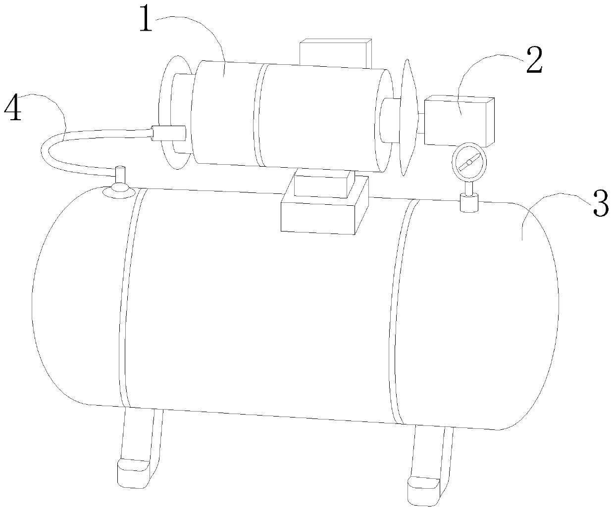
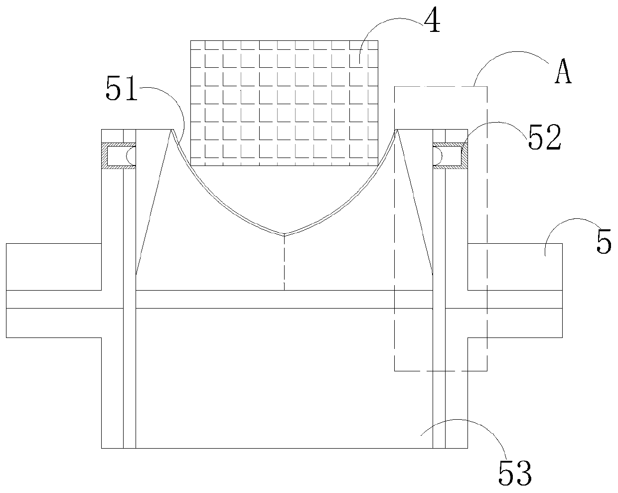
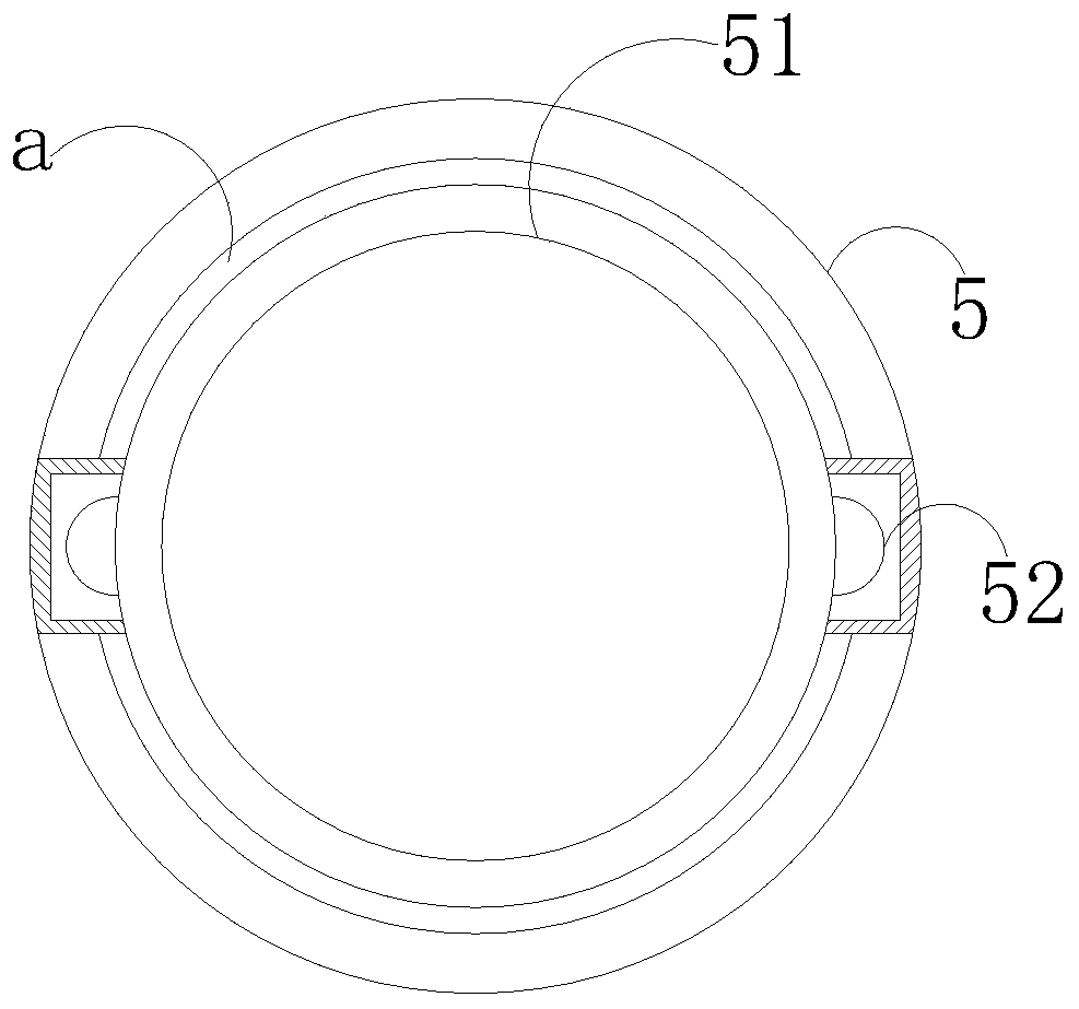
[0026] Such as Figure 1-Figure 4 , Figure 6 As shown, the present invention provides a liquid-supply gas compression equipment, the structure of which includes a hydraulic pump 1, an electric controller 2, a gas booster pump 3, an oil pipe 4, and an adapter 5. The hydraulic pump 1 is connected to the gas through the oil pipe 4 The booster pump 3 is connected, the hydraulic pump 1 and the gas booster pump 3 are both driven by the electric controller 2, and the adapters 5 are respectively installed at the interface between the oil pipe 4 and the gas booster pump 3 and the hydraulic pump 1, so that The adapter 5 is composed of a concave nozzle 51, a push block 52, and a cavity 53. Both sides of the concave nozzle 51 are connected with the push block 52, and are movably fitted inside the cavity 53 through the push block 52. The concave body nozzle 51 is in contact with the oil pipe 4, and the concave body nozzle 51 and the oil pipe 4 are movable in a horizontally advancing mann...

Embodiment 2

[0028] Such as Figure 4-Figure 5 As shown, based on Example 1, when the oil pipe is connected, the oil stain on the surface of the oil pipe is directly brought into the spacer to prevent oil spillage at the adapter. The bowl-shaped structure formed by the plate makes the connection of the oil pipe more precise, and the bowl-shaped structure is characterized by a port with a large upper part and a smaller port at the lower part. The larger port can better avoid the phenomenon of oil spillage in the adapter. The body tube port 51 is provided with a built-in plate 511, a spacer 512, a movable interface 513, a connecting rod 514, and a plate mouth decontamination mechanism 515. The spacer 512 is mechanically connected with the connecting rod 514 through a movable interface 513, and the plate mouth The decontamination mechanism 515 is located on the spacer 512 and is located inside the built-in board 511. The movable interface 513 is distributed on both sides, and a plate mouth de...


PUM


Abstract

The invention discloses a liquid supply type gas compression device which structurally comprises a hydraulic pump, an electric controller, a gas supercharging pump, an oil pipe and adapters. The hydraulic pump is connected with the gas supercharging pump through the oil pipe. The hydraulic pump and the gas supercharging pump are driven through the electric controller. The adapters are installed atthe joint of the oil pipe and the gas supercharging pump and the joint of the oil pipe and the hydraulic pump. Each adapter is composed of a concave body pipe opening, push blocks and a cavity, wherein the two sides of the concave body pipe opening are connected with the push blocks and are movably matched in the cavity through the push blocks. By means of the liquid supply gas compression device, the concave body pipe openings are matched in the cavities through the push blocks on the two sides, the oil pipe clamping width is increased, the oil pipe is better fixed in the adapters, a partition bar, an internal plate, a movable connector and a connecting rod arranged on each concave body pipe opening are matched, wherein the internal plate and the partition bar are opened with the size the same with an opening of the oil pipe, when the oil pipe is connected in, oil dirt on the surface of the oil pipe is directly brought into the partition bars, and the oil overflow phenomenon of the adapters is prevented.

Description

technical field [0001] The invention relates to the field of petrochemical general machinery, in particular, it is a liquid supply type gas compression equipment. Background technique [0002] Liquid-supply gas compression equipment uses hydraulic pressure as the driving power source to pressurize nitrogen with a certain pressure. When the pressure exceeds the outlet pressure, it reaches the rated displacement. This liquid-supply gas compression equipment is mainly used in petrochemical In terms of machinery, it provides stable driving pressure for petrochemical machinery. Petrochemical machinery is generally used in outdoor environments. When operating outside, for direct liquid supply, due to the large amount of dust particles outside, oil spills often occur at the joint seal of the oil pipe. In some cases, the oil on the surface meets the dust particles to easily form oil sludge, and the accumulation of oil sludge on the surface of the interface increases the difficulty o...

Claims


Application Information

Patent Timeline
IPC IPC(8): F04B35/02F04B53/16B08B5/04B08B15/04
CPCB08B5/04B08B15/04F04B9/10F04B53/16
Inventor 黄晓平
Owner 黄晓平
Learn More