
Center test head structure

A technology of test head and thimble, which is applied in the direction of electronic circuit testing, measuring electricity, measuring devices, etc., can solve the problems of error-prone, inconvenient, skewed chip removal, etc., and achieve the effect of convenient force debugging

Pending Publication Date: 2020-07-10
HIMIT (SHENZHEN) TECH CO LTD
View PDF12 Cites 0 Cited by
  • Summary
  • Abstract
  • Description
  • Claims
  • Application Information

AI Technical Summary

Problems solved by technology

The existing chip removal method is generally to use the robot to suck or clamp the chip to take out the chip, which is inconvenient to take out, easy to miss and miss, and it is easy to affect other chips around when taking it out, causing other chips to be skewed and inconvenient to take out; for products without detection, it is easy Cause NG products to flow into subsequent processes

Method used


Image

  • Center test head structure
  • Center test head structure
  • Center test head structure

Examples


Embodiment Construction

[0030] In order to make the objectives, technical solutions and advantages of the present invention clearer, the following describes the structure of a thimble test head of the present invention in further detail with reference to the accompanying drawings and embodiments. It should be understood that the specific embodiments described here are only used to explain the present invention, but not to limit the present invention.

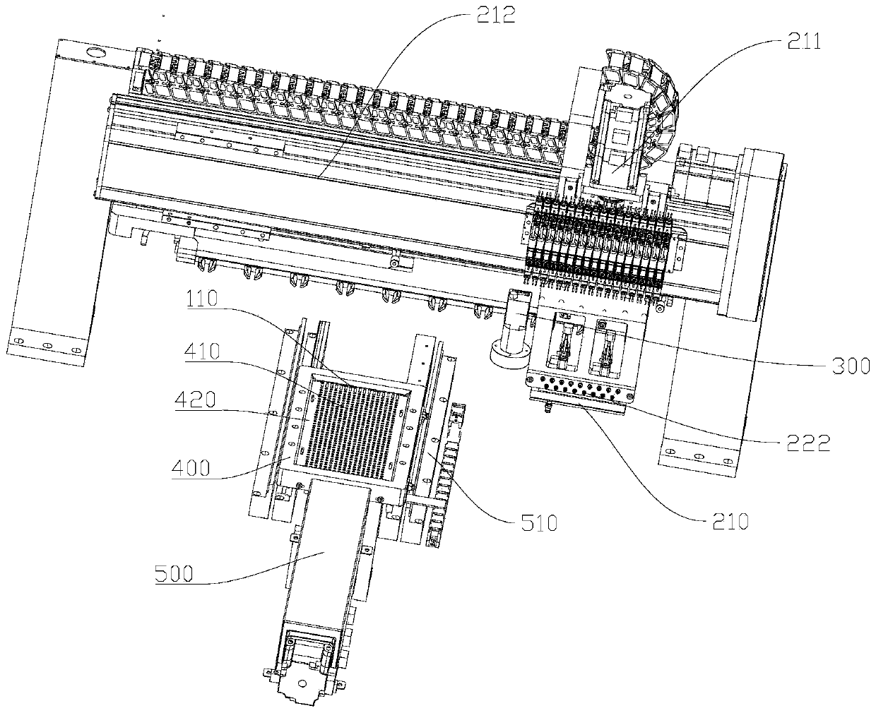
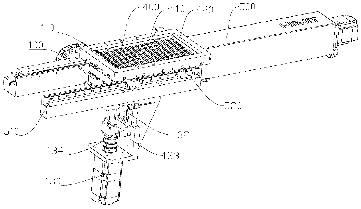
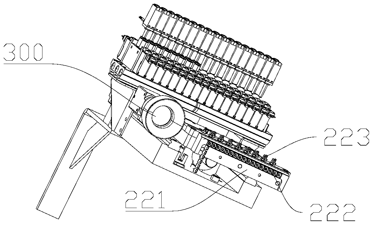
[0031] See Figure 1-Figure 6 , A thimble test head structure, used to take out the chip bonded by double-sided tape on the electroplating jig 600, the electroplating jig 600 is provided with a through hole 610 corresponding to the chip, including: thimble box 100, thimble box 100 A number of thimble pins 110 are provided inside, the thimble 110 penetrates from the top of the thimble box 100, and the thimble 110 ejects the chip from the bottom of the electroplating jig 600; the force sensor 120 is arranged in the thimble box 100 and is connected to the thi...


PUM


Abstract

The invention relates to a center test head structure for taking out a chip bonded by a double faced adhesive tape on an electroplating jig. A through hole corresponding to the chip is formed in the electroplating jig. The center test head structure comprises a center box, a force sensor, and a Z-axis moving mechanism. A plurality of centers are arranged in the center box, the centers penetrate out of the top of the center box, and the centers eject the chip out of the lower portion of the electroplating jig. The force sensor is arranged in the center box and is connected with the centers. Andthe Z-axis moving mechanism drives the centers to move along the Z axis. According to the center test head structure, the centers are ejected out of the electroplating jig through the centers, the force sensor is arranged for force detection, so that force debugging can be facilitated; the situation that the force exceeds a preset threshold value can be recorded in time; NG products are preventedfrom entering subsequent procedures; other adjacent chips can be prevented from being affected after the chips are ejected out through the centers, and high stability and convenience are achieved.

Description

Technical field [0001] The invention relates to the technical field of chip electroplating equipment, in particular to a thimble test head structure. Background technique [0002] In the chip electroplating process, the chip needs to be taken out from the electroplating jig, and after the process of front scanning, bottom CCD detection, etc., it is loaded and stacked. The existing chip extraction method generally uses a robot to pick up or clamp the chip to remove the chip. It is inconvenient to remove, easy to miss and miss, and easily affects other surrounding chips when removing, resulting in inconvenient removal of other chips. Cause NG products to flow into subsequent processes. Summary of the invention [0003] In view of the above situation, it is necessary to provide a thimble test head structure that is convenient to take out the chip and has a detection function. [0004] In order to solve the above technical problems, the technical solution adopted by the present invent...

Claims


Application Information

Patent Timeline
Patent Type & Authority Applications(China)
IPC IPC(8): G01N21/956G01R1/04G01R31/28
CPCG01N21/956G01R31/2851G01R1/0408
Inventor 蒋海兵
Owner HIMIT (SHENZHEN) TECH CO LTD
Learn More