
Inner and outer layer vending machine

A vending machine, technology of inner and outer layers, applied in instruments, coin-operated equipment for distributing discrete items, coin-operated equipment for distributing discrete items, etc., can solve the problem that the space utilization of the vending machine needs to be further improved , to achieve the effect of multi-cargo capacity and cargo selectivity

Pending Publication Date: 2020-07-10
雷继晟
View PDF1 Cites 4 Cited by
  • Summary
  • Abstract
  • Description
  • Claims
  • Application Information

AI Technical Summary

Problems solved by technology

[0002] Although the prior art or inventors have developed and disclosed multiple patents for vending machines, the utilization of space for existing vending machines still needs to be further improved

Method used


Image

  • Inner and outer layer vending machine
  • Inner and outer layer vending machine
  • Inner and outer layer vending machine

Examples


Embodiment 1

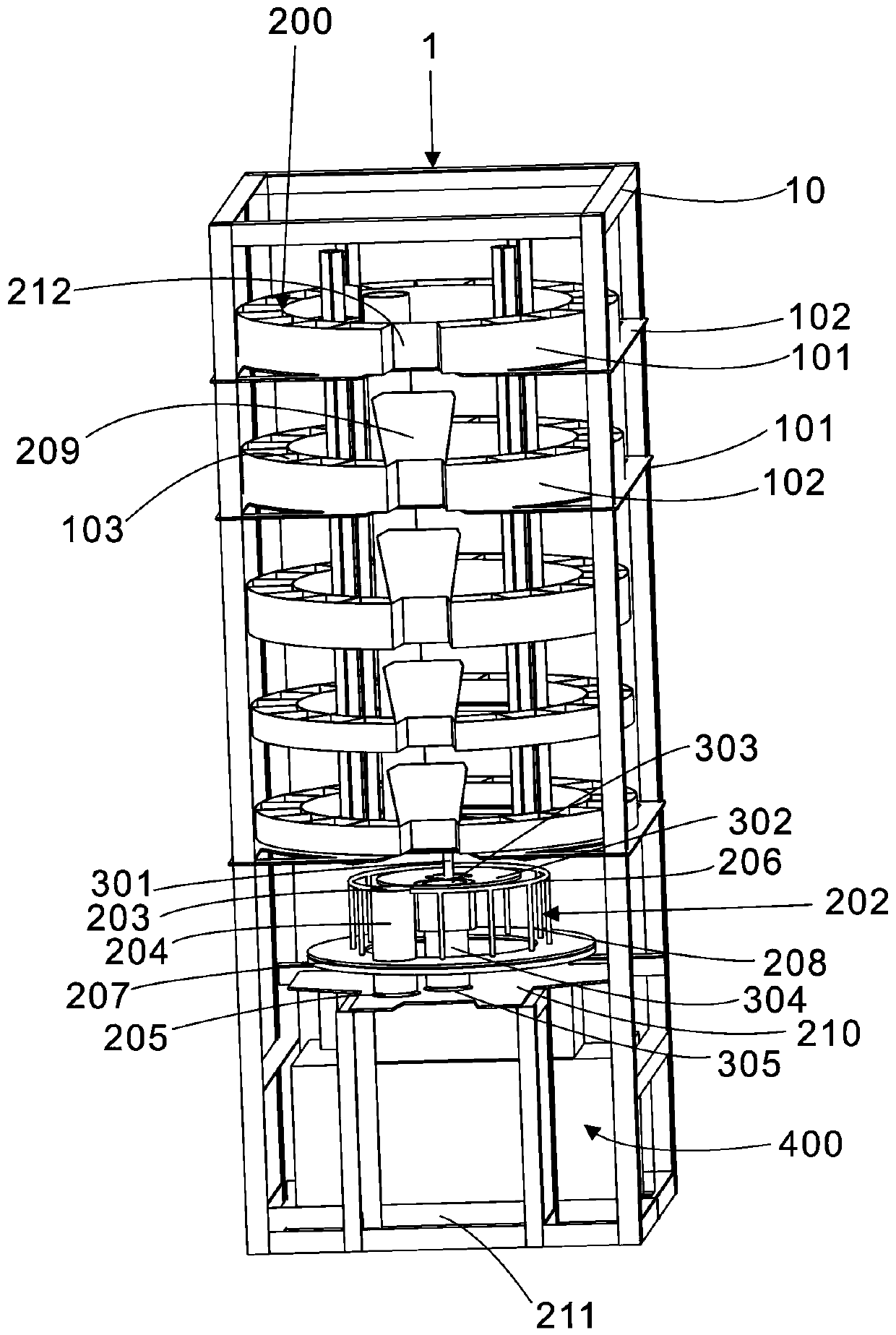
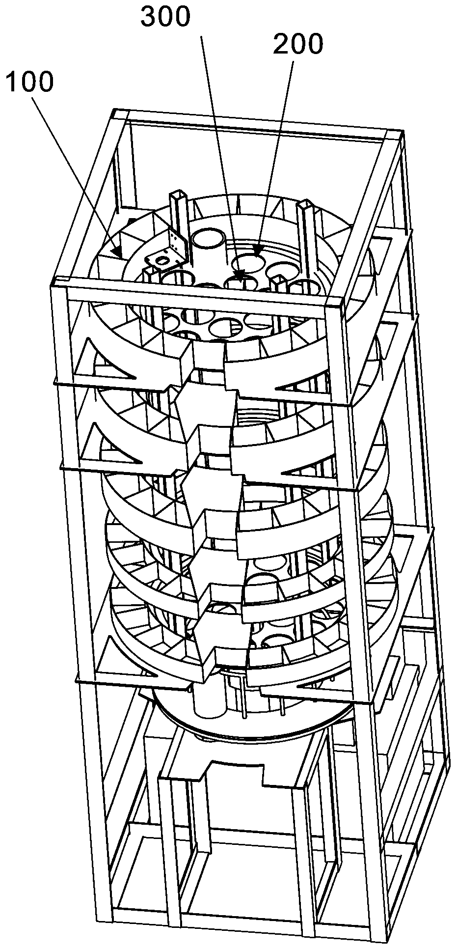
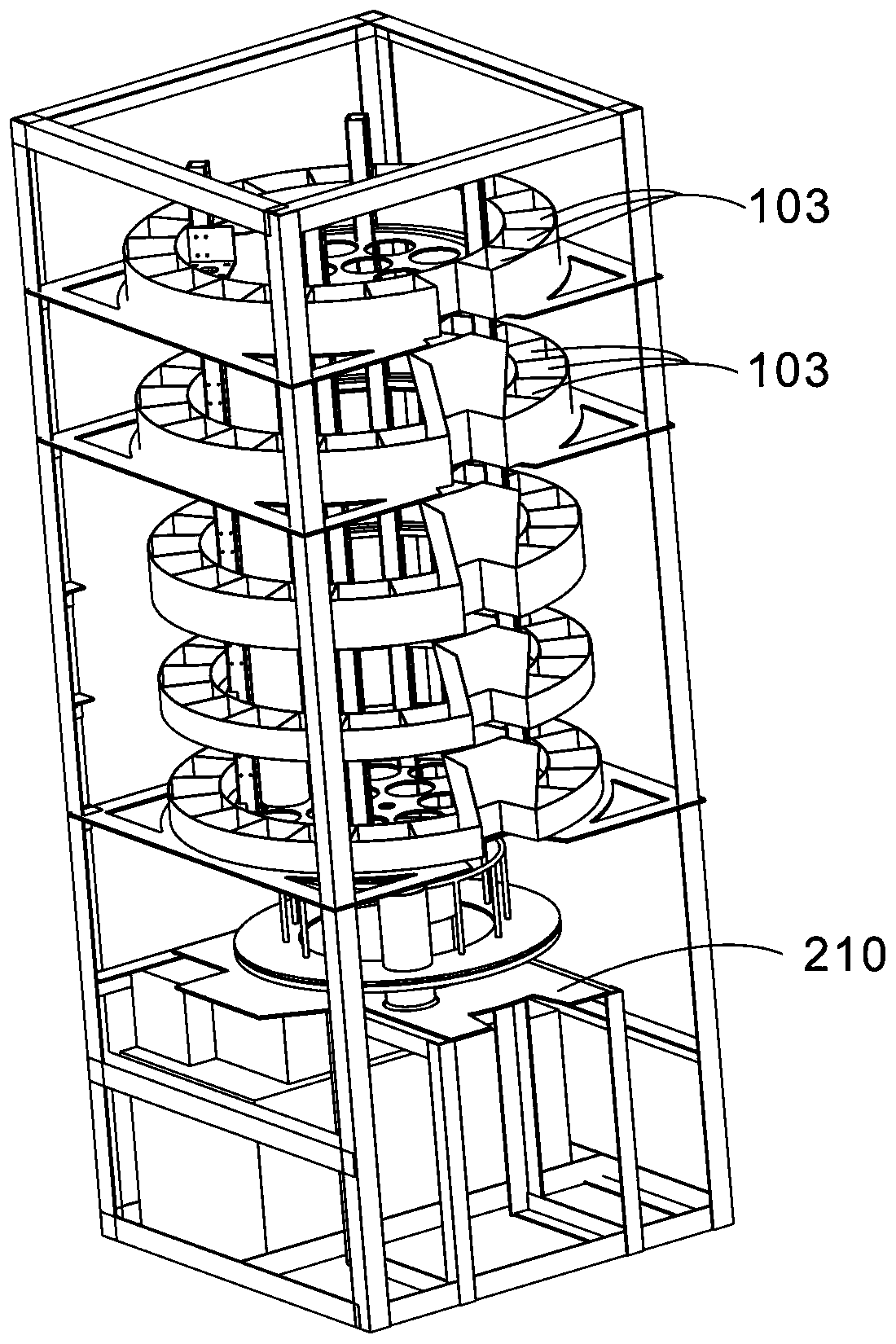
[0031] see Figure 1 to Figure 7 As shown, a vending machine with inner and outer layers includes a mechanical part and an electronic control part.

[0032] The mechanical part is provided with a box body 1, the box body 1 includes a bracket 10, and an inner layer 100 and an outer layer 200 are arranged inside the box body 1.

[0033] The outer layer 200 is provided with a plurality of annular turntables 101 and chassis 102 arranged up and down, and each annular turntable 101 and each chassis 102 form a group, forming multiple groups arranged up and down. Generally more than 3 groups can be set, and accompanying drawing 1-4 is provided with 5 groups as a kind of embodiment, can set more groups as required. Wherein each chassis 102 is fixed with the bracket 10, and the two can be directly welded or fixed by other fixing methods. Taking one group as an example, the chassis 102 is fixed on the bottom of the ring turntable 101 . The annular turntable 101 can rotate relative to ...

Embodiment 2

[0046] On the basis of Embodiment 1, in order to facilitate picking up goods, the first notch 212 in the middle is provided with a tapered slideway 209 for transitional goods falling. This makes it easier for the goods to fall along the slideway 209 when they fall. The tapered slideway 209 is beneficial to accommodate the goods and prevent the goods from falling or being stuck at the non-picking port 211 .

Embodiment 3

[0048] On the basis of Embodiment 1, in order to facilitate the refrigeration of goods, the vending machine on the inner and outer layers further includes a cooling device 400 , which is arranged at the bottom of the box body 1 . The air-conditioning device 400 can adopt the air-conditioning device 400 of a refrigerator, and use a similar refrigeration principle to transport cold air from the bottom to the upper goods.


PUM


Abstract

An inner and outer layer vending machine comprises a mechanical part and an electronic control part, the mechanical part is provided with a box body, the box body is internally provided with an innerlayer and an outer layer, the outer layer is provided with an annular rotating disc and a chassis, the annular rotating disc is provided with a plurality of through holes used for containing goods, the annular rotating disc is connected with a first motor, and the annular rotating disc is provided with a first notch; a plurality of hollow long-strip-shaped cylinders are arranged on the inner layer, each hollow long-strip-shaped cylinder is inserted into the inner layer from top to bottom, an annular bearing table is arranged under the lowest base plate, the annular bearing table is connected with a second motor, and a second notch is formed in the annular bearing table; the electronic control part is provided with a payment module and a control module, the payment module is used for sending a payment signal to the control module, and the control module is used for selectively controlling driving of the first motor and the second motor according to the payment signal. The inner layer and the outer layer are ingeniously arranged into a whole, the space of the box body is fully utilized, and more goods containing capacity and goods selectivity are achieved.

Description

technical field [0001] The invention relates to an automatic vending machine, in particular to an inner and outer layer automatic vending machine. Background technique [0002] Although the prior art or inventors have developed and disclosed a number of patents for automatic vending machines, the space utilization of existing automatic vending machines still needs to be further improved. [0003] For example, the inventor disclosed a rotary vending machine in Chinese patent document CN209168276U. The inventor found that the internal space of the rotary vending machine can still be fully utilized. Contents of the invention [0004] In view of this, in order to solve the above technical problems, the purpose of the present invention is to propose an inner and outer layer automatic vending machine that fully utilizes the space of the box body, which has more cargo capacity and cargo selection. [0005] The technical solutions adopted are: [0006] An inner and outer vending...

Claims


Application Information

Patent Timeline
Patent Type & Authority Applications(China)
IPC IPC(8): G07F11/54
CPCG07F11/54
Inventor 雷继晟雷锴
Owner 雷继晟
Learn More