Integrated terminal box of a rotary dynamoelectric machine

A technology for rotating electrical machines and junction boxes, applied in electrical components, electromechanical devices, electrical components, etc., can solve problems such as reducing the compactness of the drive system

Active Publication Date: 2020-07-10
SIEMENS AG
View PDF13 Cites 0 Cited by
  • Summary
  • Abstract
  • Description
  • Claims
  • Application Information

AI Technical Summary

Problems solved by technology

The disadvantage here is that a relatively large radial installation space must be provided in order to be able to carry out the above-mentioned maintenance and connection work on the motor
This reduces the compactness of the entire drive system especially in the aforementioned applications

Method used


Image

  • Integrated terminal box of a rotary dynamoelectric machine
  • Integrated terminal box of a rotary dynamoelectric machine
  • Integrated terminal box of a rotary dynamoelectric machine

Examples


Embodiment Construction

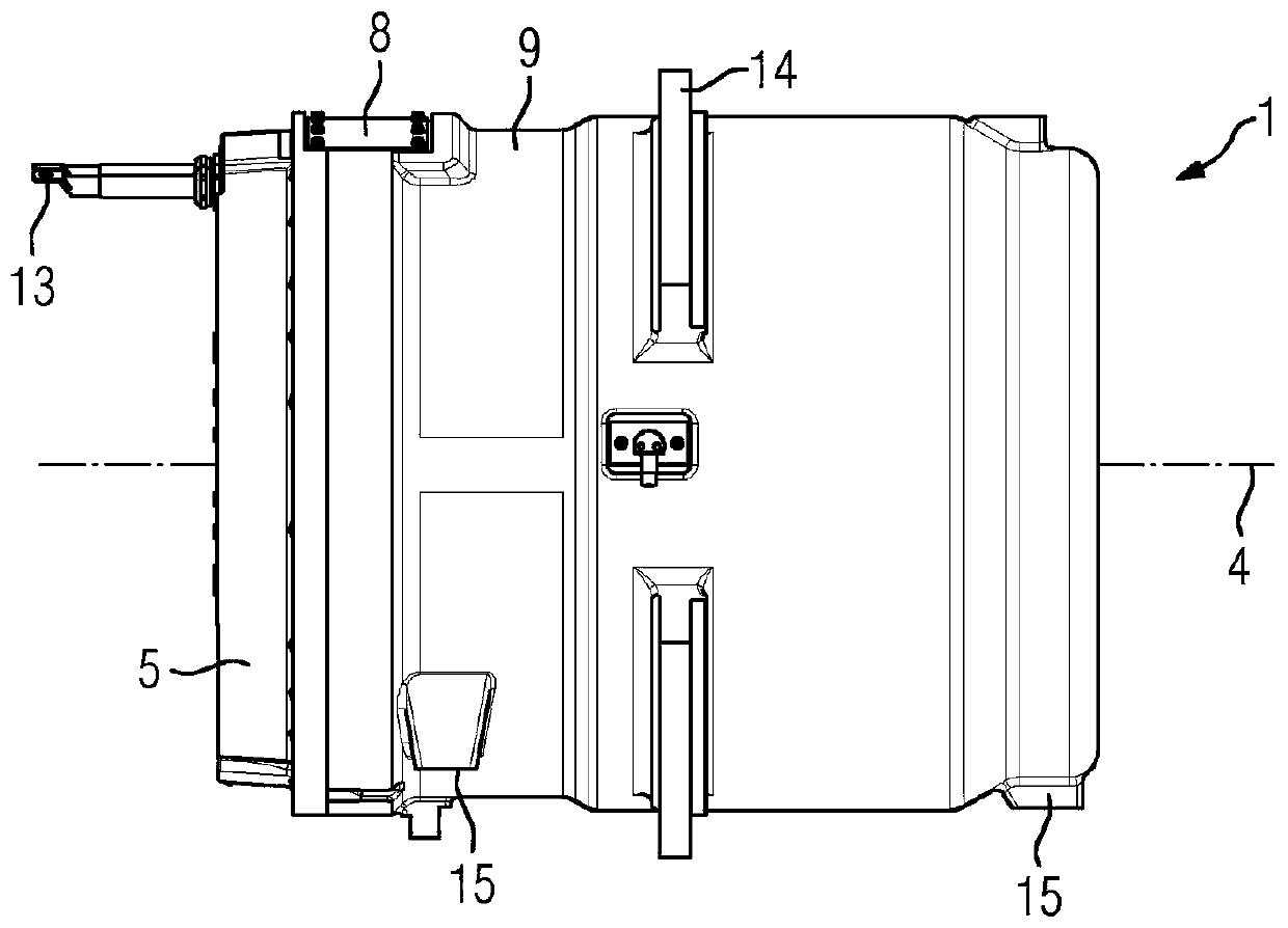
[0030] figure 1 A side view of the electric machine 1 is shown, the external connecting lines 13 of which protrude parallel to the axis 4 through the bearing shield 5 into the electric machine 1 . Viewed in the circumferential direction, the flange element 14 is located section by section in the middle region of the housing 9 of the electric machine 1 , by means of which the machine 1 is arranged and positioned in the installation space of the vehicle or machine tool provided for this purpose. . Optional further fastening points 15 can allow additional fastening points in a correspondingly formed installation space.

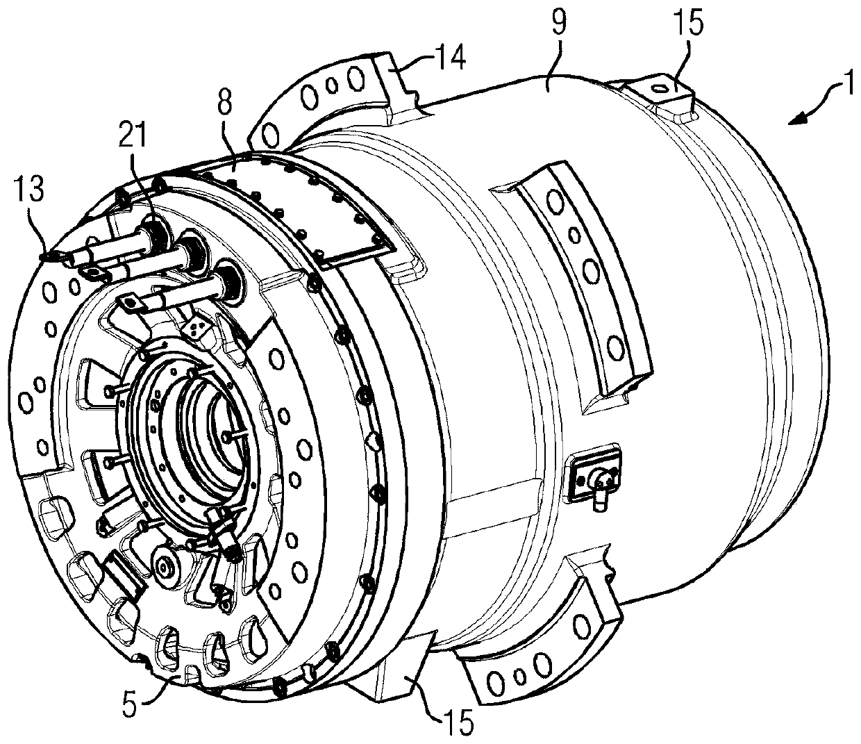
[0031] figure 2 A perspective view of the electric machine 1 is shown, wherein this view shows the inner cover 8 of the terminal box 23 which is not yet visible in this view. In this case, the external connecting wires 13 (three in this case) run through the bearing cap 5 to one connecting wire for each electrical phase.

[0032] Optionally, a plurality of c...


PUM


Abstract

The invention relates to a rotary dynamoelectric machine (1) comprising a single- or multi-phase winding system (2), which is arranged in a stator (3), wherein at least the winding connection lines (6) thereof are guided into a terminal box (23) where they can be contacted with external connection lines (13), wherein the terminal box (23) is located in the region of the end side of the stator (3),is recessed in a housing (9) of the stator (3) and is arranged axially between the stator (3) and an end shield (5).

Description

technical field [0001] The invention relates to a rotating electrical machine having a single-phase or multiphase winding system in a stator, wherein at least the winding connecting conductors of the winding system are guided into a terminal box and can be contacted there with external connecting conductors. Background technique [0002] Rotating electric machines are used in many fields of application. In vehicle technology, for example, in motor vehicles, in electric vehicles, trams, mining applications and mining trucks. There, radially and axially restricted installation space is provided for drive technology equipment. However, it must be ensured that certain maintenance tasks can be carried out in a simple manner. It is even more difficult: additional electric running mechanisms, additional components make access to the motor for maintenance work more difficult. It is therefore necessary, for example, to change the connecting lines of the motor without complex disas...

Claims


Application Information

Patent Timeline
Patent Type & Authority Applications(China)
IPC IPC(8): H02K5/22H02K5/15
CPCH02K5/15H02K5/225H02K2205/09H02K5/20
Inventor 瓦莱里娅斯·施密特
Owner SIEMENS AG
Why Eureka
Try Eureka