Efficient punching device

A punching device, high-efficiency technology, applied in transportation and packaging, boring/drilling, drilling/drilling equipment, etc., can solve the problem of low drilling efficiency, low processing efficiency and product qualification rate, and easy processing deviation and other problems to achieve the effect of avoiding low processing efficiency and high-efficiency drilling processing

Inactive Publication Date: 2020-07-14
宁波格林工艺玩具有限公司
View PDF14 Cites 1 Cited by
  • Summary
  • Abstract
  • Description
  • Claims
  • Application Information

AI Technical Summary

Problems solved by technology

[0004] In view of the above-mentioned problems in the prior art, it is now intended to provide a high-efficiency drilling device to set a stepped drill bit, and along one direction, the cross-sectional diameter of the drill bit increases or decreases sequentially, so that the variable diameter can be realized. One-time processing of cross-section holes, at the same time, a transition surface is provided at the connection between two adjacent sections of the drill bit, and a knife edge is provided on the transition surface, which can realize chamfering at the opening of the variable-section hole, that is, realize The one-time processing of the chamfering of the variable cross-section hole and its hole avoids the problems of low processing efficiency and product qualification rate caused by multiple clamping and drill replacement. In addition, the drive with multiple drill installation heads is set. The position of each drill bit installation head can be set according to the actual use requirements and the drill bit can be clamped, which realizes the simultaneous processing of multiple variable-section holes on the workpiece, and also avoids the low drilling efficiency caused by multiple clamping, and is prone to processing deviations The problem of realizing the efficient drilling of the workpiece

Method used


Image

  • Efficient punching device
  • Efficient punching device
  • Efficient punching device

Examples


Embodiment Construction

[0029] In order to make it easy to understand the technical means, creative features, goals and effects achieved by the present invention, the following examples are combined with the appended figure 1 To attach Figure 5 The technical solutions provided by the present invention are described in detail, but the following content is not intended as a limitation of the present invention.

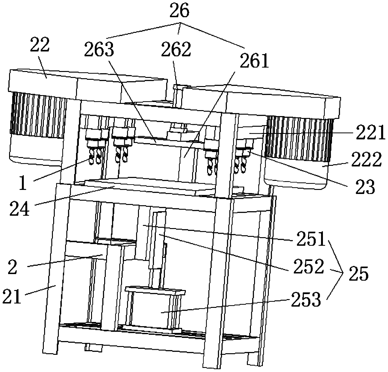
[0030] figure 1 It is a structural diagram of an embodiment of a high-efficiency punching device of the present invention. Such as figure 1 As shown, the high-efficiency drilling device provided in this embodiment includes: a stepped drill bit 1 and a punching assembly 2, the stepped drill bit 1 is installed on the punching assembly 2, and the stepped drill bit 1 is driven by the punching assembly 2 to move, thereby realizing The machining of holes on workpieces.

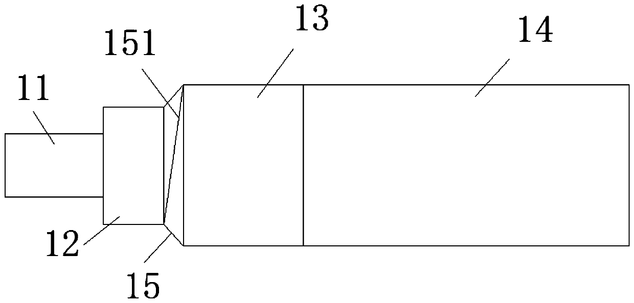
[0031] Specifically, the stepped drill bit 1 further includes a first blade segment 11, a second blade segment 12, a third bla...


PUM


Abstract

The invention provides an efficient punching device, and belongs to the technical field of automatic punching machining. The efficient punching device comprises a stepped drill bit and a punching assembly, wherein cross-sectional diameters of all sections of the stepped drill bit are sequentially increased or decreased in one direction, transition surfaces with knife edges are arranged between every two adjacent sections, so that one-time machining on a variable cross-sectional hole and orifice chamfering of the variable cross-sectional hole on a workpiece can be realized, the problems of lowmachining efficiency and poor product quality caused by multiple clamping or replacement of the drill bit are avoided, in addition, the punching assembly is arranged for mounting the stepped drill bit, the punching assembly comprises a plurality of detachably connected drill bit mounting heads, so that synchronous movement of drill bits mounted on the plurality of drill bit mounting heads is realized, one-time machining on a workpiece with a plurality of holes in different positions is achieved, the problems that machining efficiency is low and deviation is prone to occur due to multiple clamping is avoided as well, and efficient punching machining is achieved.

Description

technical field [0001] The invention relates to the technical field of automatic drilling, in particular to an efficient drilling device. Background technique [0002] People's production and life cannot be separated from the use of tools, but the production and manufacture of tools is not completed in one process. It is often necessary to process multiple parts and splicing these parts into a whole tool. Therefore, parts often need Process the mounting holes first. [0003] In order to improve the aesthetics and safety of the tool, the mounting holes on the parts are usually set as variable-section holes, such as countersunk holes, which can ensure the smoothness of the outer surface of the parts after assembly. However, in the process of machining the variable cross-section hole, because the diameters of different sections of the variable cross-section hole are different, the specifications and sizes of the drill bits used for drilling are also different. However, the cu...

Claims


Application Information

Patent Timeline
IPC IPC(8): B23B39/16B23B51/00
CPCB23B39/16B23B51/009
Inventor 王慧高
Owner 宁波格林工艺玩具有限公司
Why Eureka
Try Eureka