Selective laser melting device with electromagnetic positioning powder spreading device

A powder spreading device and laser melting technology, applied in the laser field, can solve the problems of low processing efficiency and achieve the effects of avoiding pollution waste, low processing efficiency and large limitations

Active Publication Date: 2018-11-06
谢秀英
View PDF7 Cites 0 Cited by
  • Summary
  • Abstract
  • Description
  • Claims
  • Application Information

AI Technical Summary

Problems solved by technology

[0004] In view of this, the purpose of the present invention is to overcome the defects in the prior art and provide a selective laser melting device with an electromagnetic positioning powder spreading device, which can ensure the stability of the powder spreading device and realize the precise adjustment of the

Method used


Image

  • Selective laser melting device with electromagnetic positioning powder spreading device
  • Selective laser melting device with electromagnetic positioning powder spreading device
  • Selective laser melting device with electromagnetic positioning powder spreading device

Examples


Embodiment Construction

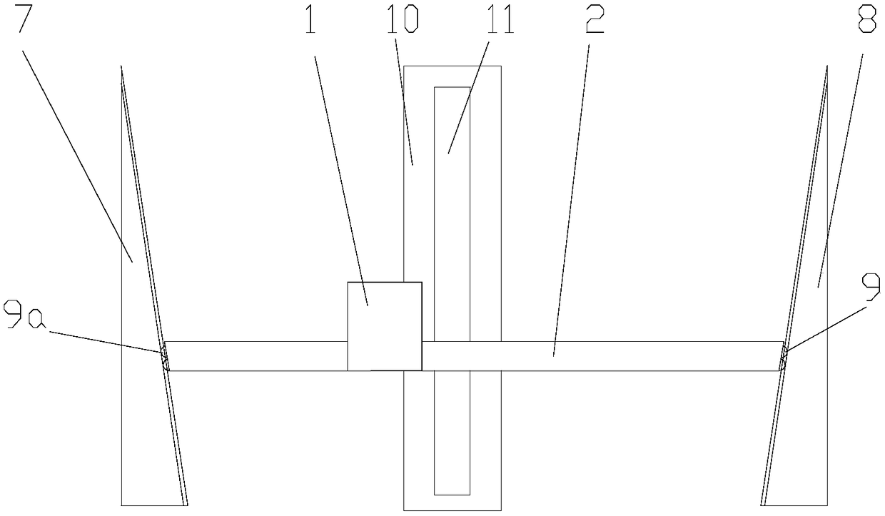
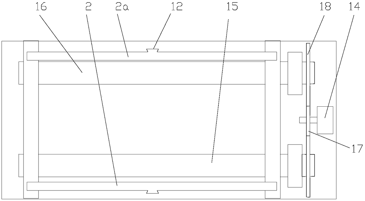
[0029] As shown in the figure, the selective laser melting device with electromagnetic positioning powder spreading device in this embodiment includes a frame (not shown), a powder spreading device 1 for laying metal powder, and a laser for selectively melting metal powder system, a horizontal guide rail for supporting the powder spreading device 1 and a vertical drive mechanism for driving the horizontal guide rail 2 to move vertically. The horizontal drive mechanism, the laser system and the horizontal guide rail 2 are relatively fixed, and the laser is a prior art, so it will not be repeated here; the horizontal guide rail 2 is strip-shaped and its length direction is arranged horizontally, There are two (including the rear horizontal guide rail 2a and the front horizontal guide rail 2) and are respectively located on both sides of the powder spreading device 1 in the longitudinal direction; driven by a horizontal drive motor, the powder spreading device 1 slides in the left...


PUM

PropertyMeasurementUnit
Top angleaaaaaaaaaa

Abstract

The invention discloses a selective laser melting device with an electromagnetic positioning powder spreading device. The device comprises a machine frame, a powder spreading device used for laying metal powder, a laser for selectively melting the metal powder, a horizontal guide rail used for supporting the powder spreading device and a vertical driving mechanism used for driving the horizontal guide rail to move vertically, and a horizontal driving mechanism which is matched with the horizontal guide rail to drive the powder spreading device to horizontally reciprocate is arranged on the powder spreading device; the vertical driving mechanism is arranged at the two ends of the horizontal guide rail, and the longitudinal section of the vertical driving mechanism is a right triangle, a right wedge-shaped seat and a wedge-shaped seat driving assembly used for driving the left wedge-shaped seat and the right wedge-shaped seat to slide along the transverse single-degree-of-freedom direction. According to the selective laser melting device, the stability of the powder spreading device can be guaranteed, and meanwhile, the height of the powder spreading device can be accurately adjusted, so that in-situ machining is realized, the problems of low machining efficiency, large limitation and the like are avoided, and the application range is enlarged.

Description

technical field [0001] The invention relates to the field of lasers, in particular to a selective laser melting device with an electromagnetic positioning powder spreading device. Background technique [0002] SLM: Selective laser melting (selective laser melting), is a kind of additive manufacturing technology. It is a rapid prototyping technology for metal powder. It can directly form metal parts with close to complete density and good mechanical properties. Its use is high The high-power laser beam processes and fuses a layer of metal powder into a shape. After the fusion is completed, the operating platform is lowered by a distance of one layer thickness, and continues to process the next layer of powder. This step is repeated until all the designated (selected to be processed) areas are melted and casted. Complete, just get a three-dimensional compound. The required products (parts) are accumulated through layer-by-layer processing in this way; in the prior art, the li...

Claims


Application Information

Patent Timeline
IPC IPC(8): B22F3/105B33Y30/00
CPCB33Y30/00B22F10/00B22F12/67B22F10/28B22F12/222B22F12/50B22F12/224B22F10/73Y02P10/25
Inventor 杨转运唐志添马波
Owner 谢秀英
Why Eureka
Try Eureka