Hydraulic torque converter

A hydraulic torque converter and hydraulic clutch technology, which is applied in the fields of mine drilling, oil and gas drilling, drilling tools, geological exploration, and coalbed methane drilling. It can solve problems such as large frictional resistance, complex internal structure, and easy sticking. To achieve the effect of increasing service life, improving safety and reliability, and avoiding pollution

Active Publication Date: 2016-04-27
CHINA PETROCHEMICAL CORP +1
View PDF5 Cites 5 Cited by
  • Summary
  • Abstract
  • Description
  • Claims
  • Application Information

AI Technical Summary

Problems solved by technology

In the process of directional drilling, domestic mud motors are mainly used for drilling operations in the form of sliding drilling. In order to balance the counter torque generated by the downhole power motor and stabilize the tool face of the downhole drilling tool assembly, the way of locking the rotary table at the wellhead is usually used. Except for the drill bit rotating to break the rock, all other drill strings including the mud motor casing do not rotate, and lie flat on the bottom of the well due to their own weight, resulting in high frictional resistance during sliding drilling, making it difficult to effectively apply WOB, and sticking is prone to occur Such as downhole safety accidents, especially in the process of guided drilling such as extended reach wells, long horizontal section horizontal wells, unconventional wells, etc., the frictional torque is large, the drill string is difficult to lift and lower, and the pressure is difficult to pressurize during drilling.
[0003] Chinese patents 201310422132.9 and 201010189645.6 both provide downhole anti-torq...

Method used


Image

  • Hydraulic torque converter
  • Hydraulic torque converter
  • Hydraulic torque converter

Examples


Embodiment 1

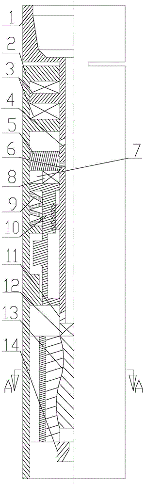
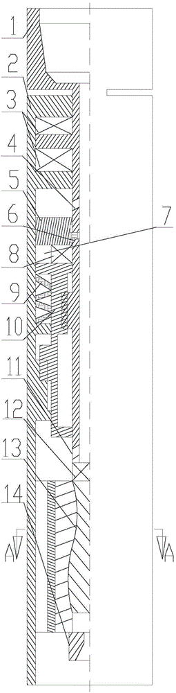
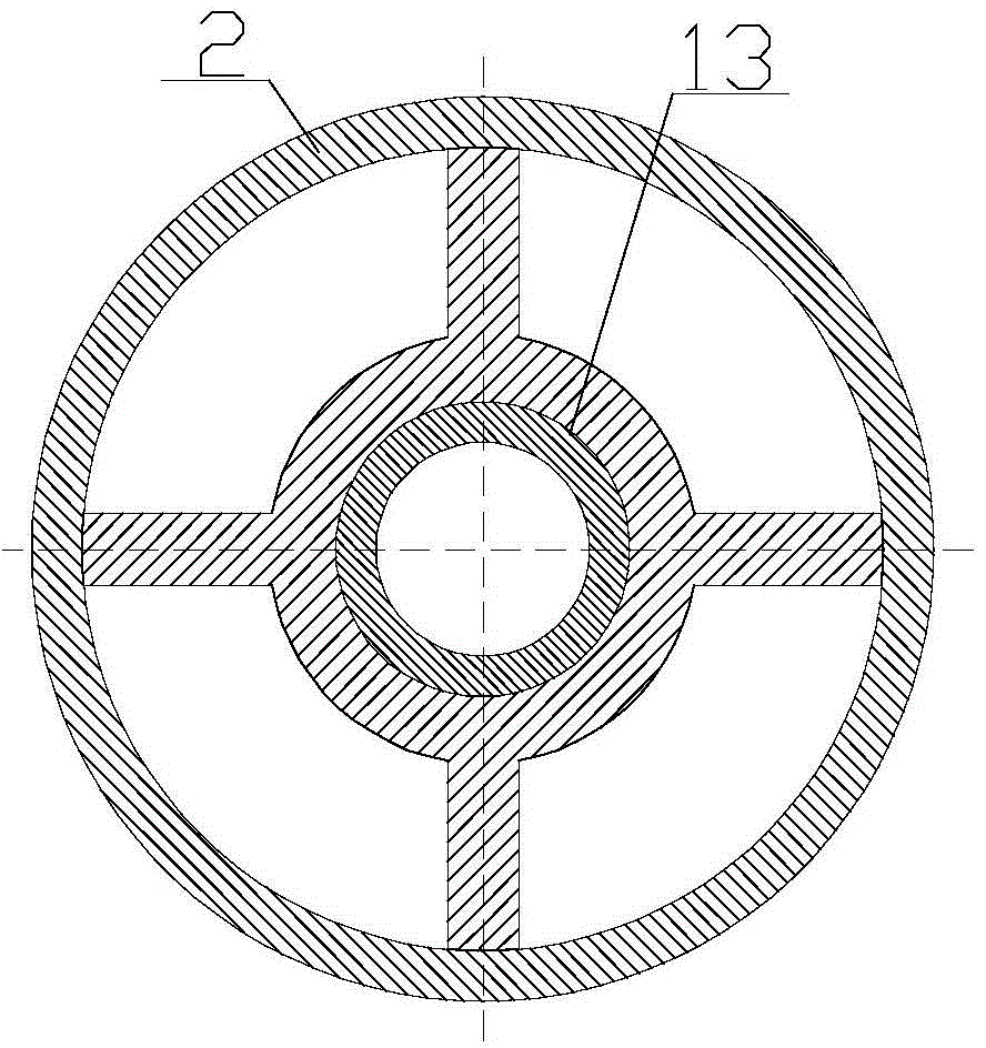
[0025] Refer to attached figure 1 with 2, The hydraulic torque converter includes a central shaft 1, an outer shell 2, bearing devices 3 and 8, a regulator 5, a spring 9, a hydraulic clutch 10, a coupling 12, a torque generator 13, and a nozzle 14. Wherein: the central shaft 1 does not have a connector, and the rest is installed inside the outer shell 2, and the central shaft 1 and the outer shell 2 form a rotating sealing fit through the bearing device 3 and the bearing convex edge. The adjuster 5 is installed in the annular cavity between the central shaft 1 and the outer shell 2, and forms a sealing fit with the central shaft 1 and the outer shell 2 in the axial direction. The positioning mechanism forms a position-limiting fit for reciprocating movement along the axial direction. The hydraulic clutch 10 connects with the regulator 5 below through the bearing device 8 . The upper and middle parts of the hydraulic clutch 10 are respectively provided with inner splines and...

Embodiment 2

[0027] On the basis of embodiment 1, refer to the appended Figure 4 , the reciprocating positioning mechanism between the regulator 5 and the central shaft 1 is an inherent positioning pin 6 on the central shaft 1, and a positioning groove is processed on the regulator 5, and the positioning groove is a continuous "N" shape evenly distributed on the inner wall of the regulator. The positioning pin 6 forms a sliding fit with the positioning groove.

[0028] The foregoing embodiment is further refined into:

[0029] The step surface is processed in the positioning groove.

[0030] The oil storage chamber 7 is preset between the regulator 5 and the hydraulic clutch 10; the lower end of the lower spline of the hydraulic clutch 10 is processed into an introduction angle.

[0031] The nozzle 14 is composed of a single nozzle body or a plurality of nozzle bodies; on the sealing surfaces of the central shaft 1 and the outer casing 2, the regulator 5 and the central shaft 1 and the ...


PUM


Abstract

The invention discloses a hydraulic torque converter and mainly relates to the field of oil and gas well drilling. The hydraulic torque converter is installed between a bottom drilling tool combination and a drill column. The hydraulic torque converter is mainly composed of a center shaft, an outer shell, bearing devices, an adjustor, a spring, a hydraulic clutch, a coupler, a torque generator and a nozzle. Due to the special structure and the special connecting function relation among the center shaft, the outer shell, the bearing devices, the adjustor, the spring, the hydraulic clutch, the coupler, the torque generator and the nozzle, the hydraulic torque converter can achieve drill column rotation on the premise that reactive torque of the bottom drilling tool combination is balanced and a tool face is stabilized and can also complete tool face adjustment or composite rotation well drilling work. The drilling speed of a well of a complex structure can be better increased, the well track control precision can be better improved, in addition, a conventional sliding well drilling manner can be changed into a rotation well drilling manner, sliding friction resistance of the drill column is effectively reduced, and the hydraulic torque converter is of great significance in improving the well drilling efficiency of the well of the complex structure. Meanwhile, the hydraulic torque converter has the beneficial effects of being simple in structure, convenient to operate and install, safe and reliable.

Description

technical field [0001] The invention mainly relates to a hydraulic torque converter in the field of drilling tools, and is especially suitable for the fields of oil and gas drilling, coal bed gas drilling, geological exploration and mine drilling. Background technique [0002] With the increasing difficulty of oil and gas field development and the rapid development of drilling technology, the number of wells with complex structures such as extended-reach wells, long horizontal wells, and multi-level lateral wells is increasing day by day, which puts forward higher requirements for drilling technology. In the process of directional drilling, domestic mud motors are mainly used for drilling operations in the form of sliding drilling. In order to balance the counter torque generated by the downhole power motor and stabilize the tool face of the downhole drilling tool assembly, the way of locking the rotary table at the wellhead is usually used. Except for the drill bit rotating...

Claims


Application Information

Patent Timeline
IPC IPC(8): E21B7/04
Inventor 李文飞李玄烨夏文安姜兰其曾强渗周延军董怀荣于承朋安庆宝
Owner CHINA PETROCHEMICAL CORP
Why Eureka
Try Eureka