Automatic fixture device for clamping shaft sleeve parts on cylindrical grinding machine

A cylindrical grinding machine and fixture device technology, which is used in grinding machines, grinding workpiece supports, machine tools designed for grinding workpiece rotating surfaces, etc. problem, to achieve the effect of ensuring coaxiality and machining accuracy

Pending Publication Date: 2020-07-14
重庆机电职业技术大学
View PDF1 Cites 1 Cited by
  • Summary
  • Abstract
  • Description
  • Claims
  • Application Information

AI Technical Summary

Problems solved by technology

Although the fixture can directly position the part to be processed by the top of the two ends of the grinding machine through the fixture at one end, as long as the grinder is started, the fixture can automatically clamp and rotate the workpiece, and the fixture can automatically loosen the workpiece after the grinder stops, but still Manual calibration is required, and the consistency between the inner hole of the shaft sleeve parts and the axis of the mandrel is poor. During processing, the parts have no clamping device, and they are easy to loosen or eccentric when rotating, resulting in the coaxiality of the workpiece. The degree requirements cannot be met, and the processing quality of the parts cannot be guaranteed

Method used


Image

  • Automatic fixture device for clamping shaft sleeve parts on cylindrical grinding machine
  • Automatic fixture device for clamping shaft sleeve parts on cylindrical grinding machine
  • Automatic fixture device for clamping shaft sleeve parts on cylindrical grinding machine

Examples


Embodiment Construction

[0017] In order to make the technical means, creative features, goals and effects achieved by the present invention easy to understand, the present invention will be further described below in conjunction with the accompanying drawings and specific embodiments.

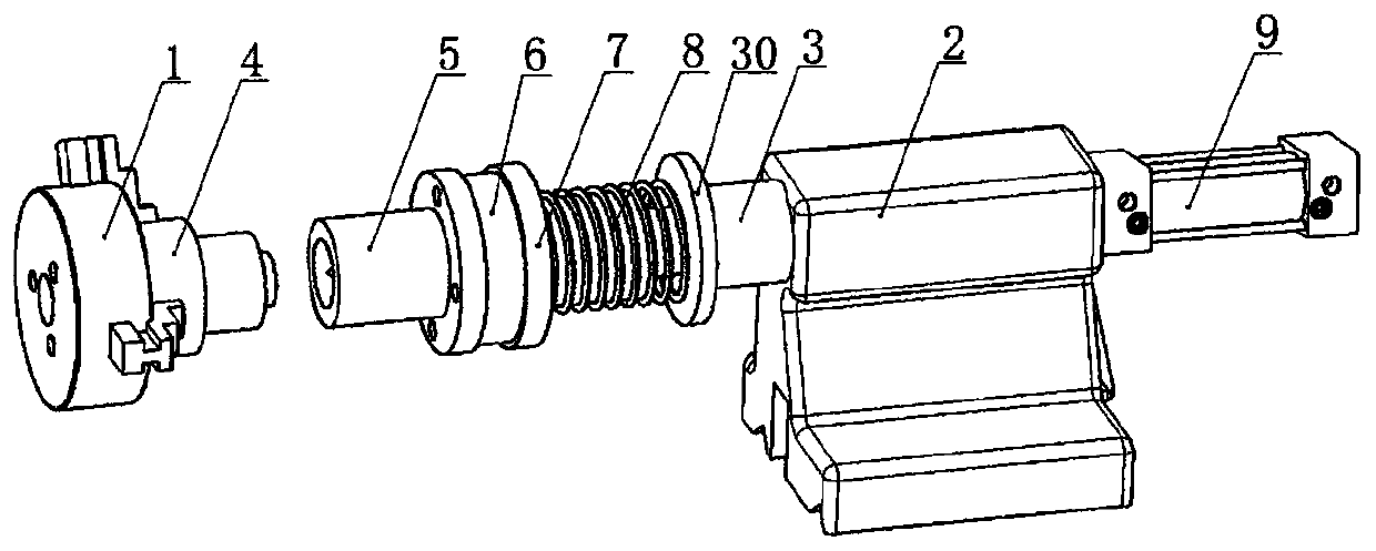
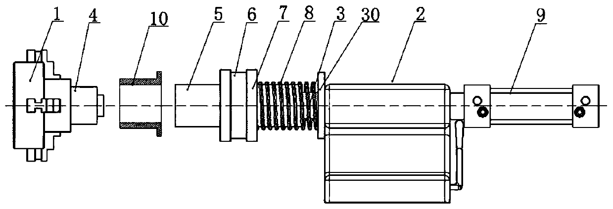
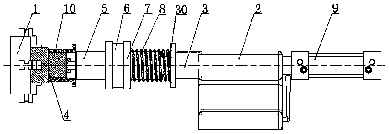
[0018] Such as figure 1 , figure 2 , image 3 , Figure 4 , Figure 5 The shown automatic fixture device is used for clamping bushing parts on the cylindrical grinding machine. The cylindrical grinder includes chuck 1, center seat 2 and tail center 3. The automatic fixture device includes mandrel 4, the first rotating and sliding bushing 5. Plane bearing 6, second rotating and sliding sleeve 7, spring 8 and cylinder 9, the mandrel 4 is fixed on the chuck 1 and coaxial with it, the mandrel 4 is in the shape of a three-stage stepped shaft, the maximum The stepped section is fixed on the chuck 1, the smallest stepped section has a center hole along the axial direction, the tail end of the tail center 3 is slidably i...


PUM


Abstract

The invention relates to the field of grinding machine processing, in particular to an automatic fixture device for clamping shaft sleeve parts on a cylindrical grinding machine. The cylindrical grinding machine comprises a chuck, a center seat and a tail center, the automatic fixture device comprises a mandrel, a first rotary sliding shaft sleeve, a plane bearing, a second rotary sliding shaft sleeve, a spring and an air cylinder, the mandrel is fixed on the chuck, the tail end of the tail center is installed on the center seat in a sliding mode, the cylinder is fixed at the tail end of the center seat, a cylinder shaft penetrates through the center seat and is connected at the tail end of the tail center, the first rotary sliding shaft sleeve, the plane bearing and the second rotary sliding shaft sleeve are sequentially arranged on the tail center from head to tail in a sleeving mode, a limiting step is further arranged on the tail center, the spring is installed between the second rotary sliding shaft sleeve and the limiting step, and shaft sleeve parts are clamped and fixed between the mandrel and the first rotary sliding shaft sleeve. According to the automatic fixture device,the automatic pressing of the parts is realized, the coaxiality of the parts during machining is guaranteed, the eccentric condition of the machined shaft sleeve parts is prevented, and the machiningprecision of the parts is improved.

Description

technical field [0001] The invention relates to the field of grinding machine processing, in particular to an automatic clamping device for clamping shaft sleeve parts on a cylindrical grinder, and is used for grinding shaft sleeve parts. Background technique [0002] With the rapid development of the economy, cylindrical grinding machine fixtures are widely used on machine tools in the industrial field, but there are also many defects in production applications. The processing error is large, which affects the quality of the product; for the processing of shaft sleeve parts with different shapes, different radial dimensions or different axial dimensions, in order to realize the clamping of the workpiece, it is often necessary to replace the fixture device, which virtually increases the fixture Design manufacturing cost and production preparation cycle, increase production cost. Or some grinding machine fixtures, when clamping or unloading, the loading and unloading time of...

Claims


Application Information

Patent Timeline
IPC IPC(8): B24B5/04B24B5/35B24B41/06
CPCB24B5/04B24B5/35B24B41/062
Inventor 张利国张华薛锋李波罗文杜桌霖陈俊豪李长春吕佳阳邓江山周会佳
Owner 重庆机电职业技术大学
Why Eureka
Try Eureka